 |
am6zzw00000750
DTC B1D75:62
id080200827900
System Malfunction Location
Detection Condition
Possible Causes
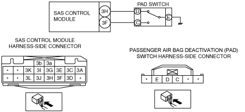
System wiring diagram
am6zzw00000750
|
Diagnostic Procedure
|
Step |
Inspection |
Action |
|
|---|---|---|---|
|
1
|
INSPECT PAD SWITCH CONNECTOR
• Switch the ignition to off.
• Disconnect the negative battery cable and wait for 1 min or more.
• Disconnect the PAD switch connector.
• Inspect the PAD switch connector. (Corrosion, damage, and disconnected pins)
• Is there any malfunction of the PAD switch connector?
|
Yes
|
Replace the PAD switch wiring harness.
|
|
No
|
Go to the next step.
|
||
|
2
|
INSPECT PAD SWITCH
• Inspect the PAD switch.
• Is the PAD switch normal?
|
Yes
|
Go to the next step.
|
|
No
|
Replace the PAD switch.
|
||
|
3
|
INSPECT WIRING HARNESS BETWEEN PAD SWITCH AND SAS CONTROL MODULE
• Remove the column cover.
• Disconnect the clock spring.
• Remove the glove compartment.
• Disconnect the passenger-side air bag module connector.
• Disconnect the driver and passenger-side side air bag module connectors.
• Remove the C-pillar trim. (4SD)
• Remove the headliner. (5HB, WGN)
• Disconnect the driver and passenger-side curtain air bag module connectors.
• Remove the B-pillar lower trim. (4SD)
• Disconnect the driver and passenger-side pre-tensioner seat belt connectors.
• Remove the rear console.
• Disconnect the SAS control module connectors.
• Inspect the wiring harness between SAS control module terminal 3H and PAD switch terminal D, SAS control module terminal 3F and PAD switch terminal C for the following:
• Is the wiring harness normal?
|
Yes
|
Go to the next step.
|
|
No
|
Replace the wiring harness between the SAS control module and PAD switch.
|
||
|
4
|
INSPECT WIRING HARNESS BETWEEN PAD SWITCH AND BODY GROUND
• Inspect for continuity between PAD switch terminal E and body ground.
• Is there continuity?
|
Yes
|
Go to the next step.
|
|
No
|
Replace the wiring harness between the PAD switch and body ground.
|
||
|
5
|
PERFORM SAS CONTROL MODULE DTC INSPECTION
• Reconnect all disconnected connectors.
• Connect the negative battery cable.
• Switch the ignition to ON.
• Clear the DTC for the SAS control module using the M-MDS.
(See CLEARING DTC.)
• Perform the DTC inspection for the SAS control module using the M-MDS.
(See DTC DISPLAY.)
• Are the same DTCs present?
|
Yes
|
Replace the SAS control module.
|
|
No
|
DTC troubleshooting completed.
|
||