STEP
INSPECTION
ACTION
1
• Start the engine.
• Release the parking brake.
• Does the brake system warning light turn off?
Yes
Troubleshooting completed.
No
Go to the next step.
2
• Does the brake fluid need replenishment?
Yes
Add brake fluid.
No
Vehicles with brake override system, without malfunction warning light
• Go to the next step.
Others
• Go to Step 4.
3
• Reactive the DTC of PCM using M-MDS.
• Is the DTC P0571:00 or P0703:00 (except MZR-CD 2.2) detected?
Yes
Go to the applicable DTC troubleshooting procedure.
(See DTC P0571:00 [MZR 2.0 DISI].)
(See DTC P0703:00 [MZR 2.0 DISI].)
(See DTC P0571:00 [MZR-CD 2.2].)
No
Go to the next step.
4
• Inspect the DTC for the instrument cluster ON-BOARD DIAGNOSTIC SYSTEM.
• Have DTCs U0415:68 or U0415:92 been recorded in memory?
Yes
Inspect the DTC for the instrument cluster.
No
Go to the next step.
5
• Inspect the DTC for the instrument cluster ON-BOARD DIAGNOSTIC SYSTEM.
• Have DTCs U0140:00 been recorded in memory?
Yes
Inspect the DTC for the instrument cluster.
No
Go to the next step.
6
• Inspect the followings:
-
― Brake fluid level sensor― Parking brake switch― Wiring harness between brake fluid level sensor and BCM― Wiring harness between parking brake switch and BCM
• Is there any malfunction?
Yes
Repair or replace malfunctioning part.
No
Go to the next step.
7
• Disconnect the negative battery cable.
• Measure the resistance between the DLC-2 terminals F and E.
• Is the resistance below 60 ohms?
Yes
Go to the next step.
No
Go to Step 9.
8
• Disconnect the negative battery cable.
• Inspect the DLC-2 terminals F and E for short to power supply or GND.
• Is there any malfunction?
Yes
Inspect the wiring harness and CAN system-related module.
Repair or replace the malfunctioning part.
No
Replace the instrument cluster.
9
• Switch the ignition to off.
• Inspect the instrument cluster connector terminals for poor connection (such as damaged/pulled-out pins, and corrosion).
• Are the terminals normal?
Yes
Go to the next step.
No
Repair or replace the terminal.
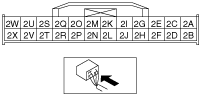
10
• Disconnect the negative battery cable.
• Measure the resistance between the instrument cluster connector terminals 2X and 2W.
• Is the resistance 114—126 ohms?
Yes
Inspect the wiring harness and CAN system-related module.
Repair or replace the malfunctioning part.
No
Replace the instrument cluster.