|
1
|
VERIFY RELATED SERVICE INFORMATION AVAILABILITY
• Verify related Service Information availability.
• Is any related Service Information available?
|
Yes
|
Perform repair or diagnosis according to the available Service Information.
• If the vehicle is not repaired, go to the next step.
|
|
No
|
Go to the next step.
|
|
2
|
VERIFY RELATED PENDING CODE AND/OR DTC
• Switch the ignition to off, then to ON (engine off).
• Perform the Pending Trouble Code Access Procedure and DTC Reading Procedure.
• Is the PENDING CODE/DTC P0703:00 also present?
|
Yes
|
Go to the applicable PENDING CODE or DTC inspection.
|
|
No
|
Vehicles without advanced keyless entry and push button start system:
• Go to Step 4.
Vehicles with advanced keyless entry and push button start system:
• Go to the next step.
|
|
3
|
VERIFY STORED DTC IN ABS HU/CM OR DSC HU/CM
• Retrieve the ABS HU/CM or DSC HU/CM DTC using the M-MDS.
• Are any DTCs present?
|
Yes
|
Go to the applicable DTC inspection.
|
|
No
|
Vehicles without advanced keyless entry and push button start system:
• Go to Step 5.
Vehicles with advanced keyless entry and push button start system:
• Go to the next step.
|
|
4
|
VERIFY STORED DTC IN KEYLESS CONTROL MODULE
• Switch the ignition to off, then to ON (engine off).
• Depress and release the brake pedal several times.
• Retrieve the keyless control module DTC using the M-MDS.
• Is the DTC C0040:29 present?
|
Yes
|
Go to the applicable DTC inspection.
|
|
No
|
Go to the next step.
|
|
5
|
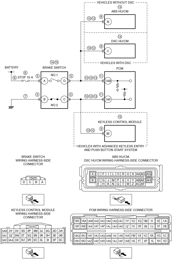
INSPECT BRAKE SWITCH CONNECTOR CONDITION
• Switch the ignition to off.
• Disconnect the brake switch connector.
• Inspect for poor connection (such as damaged/pulled-out pins, corrosion).
• Is there any malfunction?
|
Yes
|
Repair or replace the connector and/or terminals, then go to Step 16.
|
|
No
|
Go to the next step.
|
|
6
|
INSPECT BRAKE SWITCH POWER SUPPLY CIRCUIT FOR SHORT TO GROUND OR OPEN CIRCUIT
• Brake switch connector is disconnected.
• Measure the voltage at the brake switch terminal A (wiring harness-side).
• Is the voltage B+?
|
Yes
|
Go to the next step.
|
|
No
|
Inspect the STOP 10 A fuse.
• If the fuse is melt:
-
― Repair or replace the wiring harness for a possible short to ground.
― Replace the fuse.
• If the fuse is deterioration:
-
― Replace the fuse.
• If the fuse is normal:
-
― Repair or replace the wiring harness for a possible open circuit.
Go to Step 16.
|
|
7
|
INSPECT BRAKE SWITCH GROUND CIRCUIT FOR OPEN CIRCUIT
• Brake switch connector is disconnected.
• Inspect for continuity between brake switch terminal B (wiring harness-side) and body ground.
• Is there continuity?
|
Yes
|
Go to the next step.
|
|
No
|
Repair or replace the wiring harness for a possible open circuit, then go to Step 16.
|
|
8
|
INSPECT ABS HU/CM OR DSC HU/CM CONNECTOR CONDITION
• Disconnect the ABS HU/CM or DSC HU/CM connector.
• Inspect for poor connection (such as damaged/pulled-out pins, corrosion).
• Is there any malfunction?
|
Yes
|
Repair or replace the connector and/or terminals, then go to Step 16.
|
|
No
|
Vehicles without advanced keyless entry and push button start system:
• Go to Step 10.
Vehicles with advanced keyless entry and push button start system:
• Go to the next step.
|
|
9
|
INSPECT KEYLESS CONTROL MODULE CONNECTOR CONDITION
• Disconnect the keyless control module connector.
• Inspect for poor connection (such as damaged/pulled-out pins, corrosion).
• Is there any malfunction?
|
Yes
|
Repair or replace the connector and/or terminals, then go to Step 16.
|
|
No
|
Go to the next step.
|
|
10
|
INSPECT BRAKE SWITCH SIGNAL CIRCUIT FOR SHORT TO GROUND
• Brake switch connector is disconnected.
• ABS HU/CM connector is disconnected. (vehicles without DSC)
• DSC HU/CM connector is disconnected. (vehicles with DSC)
• Keyless control module connector is disconnected. (vehicles with advanced keyless entry and push button start system)
• Inspect for continuity between the following terminals (wiring harness-side) and body ground:
-
― Brake switch terminal D
― Brake switch terminal C
• Is there continuity?
|
Yes
|
If the short to ground circuit could be detected:
• Repair or replace the wiring harness for a possible short to ground.
If the short to ground circuit could not be detected:
• Replace the PCM (short to ground in the PCM internal circuit).
Go to Step 16.
|
|
No
|
Go to the next step.
|
|
11
|
INSPECT PCM CONNECTOR CONDITION
• Disconnect the PCM connector.
• Inspect for poor connection (such as damaged/pulled-out pins, corrosion).
• Is there any malfunction?
|
Yes
|
Repair or replace the connector and/or terminals, then go to Step 16.
|
|
No
|
Go to the next step.
|
|
12
|
INSPECT BRAKE SWITCH SIGNAL CIRCUIT FOR SHORT TO POWER SUPPLY
• Brake switch and PCM connectors are disconnected.
• ABS HU/CM connector is disconnected. (vehicles without DSC)
• DSC HU/CM connector is disconnected. (vehicles with DSC)
• Keyless control module connector is disconnected. (vehicles with advanced keyless entry and push button start system)
• Switch the ignition to ON (engine off).
• Measure the voltage at the following terminals (wiring harness-side):
-
― Brake switch terminal D
― Brake switch terminal C
• Is there any voltage?
|
Yes
|
Repair or replace the wiring harness for a possible short to power supply, then go to Step 16.
|
|
No
|
Go to the next step.
|
|
13
|
INSPECT BRAKE SWITCH SIGNAL CIRCUIT FOR OPEN CIRCUIT
• Brake switch and PCM connectors are disconnected.
• ABS HU/CM connector is disconnected. (vehicles without DSC)
• DSC HU/CM connector is disconnected. (vehicles with DSC)
• Keyless control module connector is disconnected. (vehicles with advanced keyless entry and push button start system)
• Switch the ignition to off.
• Inspect for continuity between the following terminals (wiring harness-side):
-
― Brake switch terminal D—PCM terminal 1AB
― Brake switch terminal C—PCM terminal 1AF
• Is there continuity?
|
Yes
|
Go to the next step.
|
|
No
|
Repair or replace the wiring harness for a possible open circuit, then go to Step 16.
|
|
14
|
INSPECT ABS HU/CM OR DSC HU/CM
• Reconnect all disconnected connectors.
• Switch the ignition to ON (engine off).
• Measure the voltage at the ABS HU/CM terminal N (wiring harness-side). (Vehicles without DSC)
• Measure the voltage at the DSC HU/CM terminal C (wiring harness-side). (Vehicles with DSC)
|
Yes
|
Vehicles without advanced keyless entry and push button start system:
• Replace the brake switch, then go to Step 16.
Vehicles with advanced keyless entry and push button start system:
• Go to the next step.
|
|
No
|
Vehicles without DSC:
• Replace the ABS HU/CM, then go to Step 16.
Vehicles with DSC:
• Replace the DSC HU/CM, then go to Step 16.
|
|
15
|
INSPECT KEYLESS CONTROL MODULE
• Measure the voltage at the keyless control module terminal 3E (wiring harness-side).
|
Yes
|
Replace the brake switch, then go to the next step.
|
|
No
|
Replace the keyless control module, then go to the next step.
|
|
16
|
VERIFY DTC TROUBLESHOOTING COMPLETED
• Make sure to reconnect all disconnected connectors.
• Clear the DTC from the PCM memory using the M-MDS.
• Switch the ignition to ON (engine off).
• Depress and release the brake pedal for 15 smore than 5 times.
• Perform the DTC Reading Procedure.
• Is the same DTC present?
|
Yes
|
Replace the PCM, then go to the next step.
|
|
No
|
Go to the next step.
|
|
17
|
VERIFY AFTER REPAIR PROCEDURE
• Perform the “AFTER REPAIR PROCEDURE”.
• Are any DTCs present?
|
Yes
|
Go to the applicable DTC inspection.
|
|
No
|
DTC troubleshooting completed.
|