|
ac5wzw00012275
DTC P0299:00 [PCM (SKYACTIV-D 2.2)]
id0102j5148500
Engine Type
|
Item |
Reference |
|---|---|
|
Fuel injector (6 pin type), without SCR System
|
|
|
Fuel injector (6 pin type), with SCR System
|
Fuel Injector (6 pin type), Without SCR System
Details on DTCs
|
System malfunction location |
Small-type turbocharger area control system: Charging deficiency |
|
|---|---|---|
|
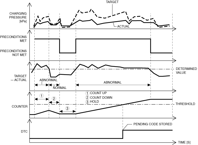
Detection condition
|
Determination condition
|
• As the result of comparing the actual boost pressure with the target boost pressure, the actual boost pressure is lower or more than the specification compared to the target boost pressure for a continuous 7 s.
|
|
Preconditions
|
• All of the following conditions are met when diesel particulate filter regeneration control is stopped during boost control feedback
|
|
|
Drive cycle
|
• 2
|
|
|
Self-test type
|
• CMDTC self test
|
|
|
Sensor/unit used
|
• MAP sensor
|
|
|
Fail-safe
|
• Not applicable
|
|
|
Vehicle status when DTCs are output
|
• Not applicable
|
|
|
Possible cause
|
• PCM input signal error
• Exhaust gas leakage from exhaust system
• Air leakage from intake-air system
• Malfunction in vacuum piping and positive pressure piping of compressor bypass valve
• Regulating valve actuator malfunction
• Variable turbine geometry turbocharger actuator malfunction
• Compressor bypass solenoid valve malfunction
• Regulating valve actuator position sensor malfunction
• Variable turbine geometry turbocharger actuator position sensor malfunction
• Turbocharger malfunction (small-type turbine, small-type compressor, large-type turbine, large-type compressor)
• PCM malfunction
|
|
System Wiring Diagram
Function Explanation (DTC Detection Outline)
ac5wzw00012275
|
Repeatability Verification Procedure
PID Item/Simulation Item Used in Diagnosis
PID
|
Item name |
Outline |
Unit |
Display/condition |
|---|---|---|---|
|
INTK_MAPA
|
Manifold absolute pressure (No.2)
|
kPa
|
• Displays the manifold absolute pressure (No.2).
|
|
MAP_DSD
|
Manifold absolute pressure (No.2) desired value
|
kPa
|
• Displays the manifold absolute pressure (No.2) desired value.
|
|
REGVP
|
Regulating valve actuator position
|
mm
|
• Displays the regulating valve actuator position.
|
|
REGVP_DSD
|
Target value for regulating valve actuator position sensor
|
mm
|
• Displays the target value for the regulating valve actuator position.
|
|
VGTURB_ACT
|
Variable turbine geometry turbocharger actuator position
|
%
|
• Displays the variable turbine geometry turbocharger actuator position.
|
Simulation item
|
Item name |
Outline |
Unit |
Display/condition |
|---|---|---|---|
|
VGTURB_DSD
|
Variable turbine geometry turbocharger actuator position
|
%
|
• Changes % and forcibly drives/stops the variable turbine geometry turbocharger actuator.
|
Function Inspection Using M-MDS
|
Step |
Inspection |
Results |
Action |
|---|---|---|---|
|
1
|
PURPOSE: VERIFY DTC CAUSING FREEZE FRAME DATA
• Is DTC P0299:00 causing the freeze frame data?
|
Yes
|
Go to the next step.
|
|
No
|
Inspect the DTC causing the freeze frame data.
|
||
|
2
|
PURPOSE: RECORD VEHICLE STATUS AT TIME OF DTC DETECTION TO UTILIZE WITH REPEATABILITY VERIFICATION
• Record the freeze frame data/snap shot data.
|
―
|
Go to the next step.
|
|
3
|
PURPOSE: VERIFY OTHER RELATED DTCs
• Switch the ignition OFF, and then switch it ON (engine off).
• Display the DTCs using the M-MDS.
• Has any DTC other than P0299:00 been stored?
|
Yes
|
Repair the malfunctioning location according to the applicable DTC troubleshooting.
|
|
No
|
Go to the next step.
|
||
|
4
|
PURPOSE: VERIFY MAP SENSOR INPUT SIGNAL
• Start the engine and warm it up.
• Display the following PIDs using the M-MDS.
• Are the monitoring values normal?
|
Yes
|
Go to the troubleshooting procedure to perform the procedure from Step 1.
|
|
No
|
Go to the next step.
|
||
|
5
|
PURPOSE: INSPECT WIRING HARNESSES AND CONNECTORS FOR RELATED-SENSOR
• Display the following PIDs using the M-MDS.
• When the PCM and MAP sensor connector are shaken, does the PID value include a PID item which has changed?
|
Yes
|
Inspect the related wiring harnesses and connectors.
• Repair or replace the malfunctioning location.
Go to the troubleshooting procedure to perform the procedure from Step 8.
|
|
No
|
Go to the troubleshooting procedure to perform the procedure from Step 1.
|
||
|
6
|
PURPOSE: DETERMINE IF MALFUNCTION IS CAUSED BY REGULATING VALVE ACTUATOR POSITION SENSOR MALFUNCTION
• Inspect the regulating valve actuator position sensor.
• Is the regulating valve actuator position sensor normal?
|
Yes
|
Go to the troubleshooting procedure to perform the procedure from Step 1.
|
|
No
|
Inspect the related wiring harnesses and connectors.
• Repair or replace the malfunctioning location.
Go to the troubleshooting procedure to perform the procedure from Step 8.
|
||
|
7
|
PURPOSE: DETERMINE IF MALFUNCTION IS CAUSED BY VARIABLE TURBINE GEOMETRY TURBOCHARGER ACTUATOR POSITION SENSOR MALFUNCTION
• Inspect the variable turbine geometry turbocharger actuator position sensor.
• Is the variable turbine geometry turbocharger actuator position sensor normal?
|
Yes
|
Go to the troubleshooting procedure to perform the procedure from Step 1.
|
|
No
|
Inspect the related wiring harnesses and connectors.
• Repair or replace the malfunctioning location.
Go to the troubleshooting procedure to perform the procedure from Step 8.
|
Troubleshooting Diagnostic Procedure
|
Step |
Inspection |
Results |
Action |
|---|---|---|---|
|
1
|
PURPOSE: INSPECT FOR EXHAUST GAS LEAKAGE FROM EXHAUST SYSTEM
• Visually inspect for exhaust gas leakage from exhaust system.
• Is the intake air system normal?
|
Yes
|
Go to the next step.
|
|
No
|
Repair or replace the malfunctioning location, then go to Step 8.
|
||
|
2
|
PURPOSE: INSPECT INTAKE AIR SYSTEM FOR AIR SUCTION
• Visually inspect the following intake air system for looseness or damage.
• Is the intake air system normal?
|
Yes
|
Go to the next step.
|
|
No
|
Repair or replace the malfunctioning location, then go to Step 8.
|
||
|
3
|
PURPOSE: INSPECT VACUUM PIPING AND POSITIVE PRESSURE PIPING OF COMPRESSOR BYPASS VALVE
• Inspect the vacuum piping and positive pressure piping of the compressor bypass valve.
• Is there hose leakage or damage in the vacuum piping and positive pressure piping?
|
Yes
|
Repair or replace the malfunctioning location, then go to Step 8.
|
|
No
|
Go to the next step.
|
||
|
4
|
PURPOSE: INSPECT COMPRESSOR BYPASS SOLENOID VALVE
• Inspect the compressor bypass solenoid valve.
• Is the compressor bypass solenoid valve normal?
|
Yes
|
Go to the next step.
|
|
No
|
Replace the compressor bypass solenoid valve, then go to Step 8.
|
||
|
5
|
PURPOSE: INSPECT REGULATING VALVE ACTUATOR
• Inspect the regulating valve actuator.
• Is the regulating valve actuator normal?
|
Yes
|
Go to the next step.
|
|
No
|
Replace the regulating valve actuator, then go to Step 8.
|
||
|
6
|
PURPOSE: INSPECT VARIABLE TURBINE GEOMETRY TURBOCHARGER ACTUATOR
• Inspect the variable turbine geometry turbocharger actuator.
• Is the variable turbine geometry turbocharger actuator normal?
|
Yes
|
Go to the next step.
|
|
No
|
Replace the variable turbine geometry turbocharger actuator, then go to Step 8.
|
||
|
7
|
PURPOSE: INSPECT TURBOCHARGER
• Inspect the turbocharger.
• Is the turbocharger normal?
|
Yes
|
Go to the next step.
|
|
No
|
Replace the turbocharger, then go to the next step.
|
||
|
8
|
PURPOSE: VERIFICATION OF VEHICLE REPAIR COMPLETION
• Reconnect all disconnected connectors and hoses.
• Refer to the [MEMORY CLEARING PROCEDURE] and clear the DTC.
• Implement the repeatability verification procedure.
• Display the DTCs using the M-MDS.
• Is DTC P0299:00 displayed?
|
Yes
|
Repeat the inspection from Step 1.
• If the malfunction recurs, replace the PCM, then go to the next step.
|
|
No
|
Go to the next step.
|
||
|
9
|
PURPOSE: VERIFY IF THERE IS ANY OTHER MALFUNCTION
• Has any other DTC or pending code been stored?
|
Yes
|
Repair the malfunctioning location according to the applicable DTC troubleshooting.
|
|
No
|
DTC troubleshooting completed.
|
Fuel Injector (6 pin type), With SCR System
Details on DTCs
|
System malfunction location |
Small-type turbocharger area control system: Charging deficiency |
|
|---|---|---|
|
Detection condition
|
Determination condition
|
• As the result of comparing the actual boost pressure with the target boost pressure, the actual boost pressure is lower or more than the specification compared to the target boost pressure for a continuous 7 s.
|
|
Preconditions
|
• All of the following conditions are met when diesel particulate filter regeneration control is stopped during boost control feedback
|
|
|
Drive cycle
|
• 2
|
|
|
Self-test type
|
• CMDTC self test
|
|
|
Sensor/unit used
|
• MAP sensor
|
|
|
Fail-safe
|
• Not applicable
|
|
|
Vehicle status when DTCs are output
|
• Not applicable
|
|
|
Possible cause
|
• PCM input signal error
• Exhaust gas leakage from exhaust system
• Air leakage from intake-air system
• Malfunction in vacuum piping and positive pressure piping of compressor bypass valve
• Regulating valve actuator malfunction
• Variable turbine geometry turbocharger actuator malfunction
• Compressor bypass solenoid valve malfunction
• Regulating valve actuator position sensor malfunction
• Variable turbine geometry turbocharger actuator position sensor malfunction
• Turbocharger malfunction (small-type turbine, small-type compressor, large-type turbine, large-type compressor)
• PCM malfunction
|
|
System Wiring Diagram
Function Explanation (DTC Detection Outline)
am6zzw00014371
|
Repeatability Verification Procedure
PID Item/Simulation Item Used in Diagnosis
PID
|
Item name |
Outline |
Unit |
Display/condition |
|---|---|---|---|
|
INTK_MAPA
|
Manifold absolute pressure (No.2)
|
kPa
|
• Displays the manifold absolute pressure (No.2).
|
|
MAP_DSD
|
Manifold absolute pressure (No.2) desired value
|
kPa
|
• Displays the manifold absolute pressure (No.2) desired value.
|
|
REGVP
|
Regulating valve actuator position
|
mm
|
• Displays the regulating valve actuator position.
|
|
REGVP_DSD
|
Target value for regulating valve actuator position sensor
|
mm
|
• Displays the target value for the regulating valve actuator position.
|
|
VGTURB_ACT
|
Variable turbine geometry turbocharger actuator position
|
%
|
• Displays the variable turbine geometry turbocharger actuator position.
|
Simulation item
|
Item name |
Outline |
Unit |
Display/condition |
|---|---|---|---|
|
VGTURB_DSD
|
Variable turbine geometry turbocharger actuator position
|
%
|
• Changes % and forcibly drives/stops the variable turbine geometry turbocharger actuator.
|
Function Inspection Using M-MDS
|
Step |
Inspection |
Results |
Action |
|---|---|---|---|
|
1
|
PURPOSE: VERIFY DTC CAUSING FREEZE FRAME DATA
• Is DTC P0299:00 causing the freeze frame data?
|
Yes
|
Go to the next step.
|
|
No
|
Inspect the DTC causing the freeze frame data.
|
||
|
2
|
PURPOSE: RECORD VEHICLE STATUS AT TIME OF DTC DETECTION TO UTILIZE WITH REPEATABILITY VERIFICATION
• Record the freeze frame data/snap shot data.
|
―
|
Go to the next step.
|
|
3
|
PURPOSE: VERIFY OTHER RELATED DTCs
• Switch the ignition OFF, and then switch it ON (engine off).
• Display the DTCs using the M-MDS.
• Has any DTC other than P0299:00 been stored?
|
Yes
|
Repair the malfunctioning location according to the applicable DTC troubleshooting.
|
|
No
|
Go to the next step.
|
||
|
4
|
PURPOSE: VERIFY MAP SENSOR INPUT SIGNAL
• Start the engine and warm it up.
• Display the following PIDs using the M-MDS.
• Are the monitoring values normal?
|
Yes
|
Go to Troubleshooting Diagnostic Procedure to perform the procedure from step 1.
|
|
No
|
Go to the next step.
|
||
|
5
|
PURPOSE: INSPECT WIRING HARNESSES AND CONNECTORS FOR RELATED-SENSOR
• Display the following PIDs using the M-MDS.
• When the PCM and MAP sensor connector are shaken, does the PID value include a PID item which has changed?
|
Yes
|
Inspect the related wiring harnesses and connectors.
• Repair or replace the malfunctioning location.
Go to Troubleshooting Diagnostic Procedure to perform the procedure from step 8.
|
|
No
|
Go to Troubleshooting Diagnostic Procedure to perform the procedure from step 1.
|
||
|
6
|
PURPOSE: DETERMINE IF MALFUNCTION IS CAUSED BY REGULATING VALVE ACTUATOR POSITION SENSOR MALFUNCTION
• Inspect the regulating valve actuator position sensor.
• Is the regulating valve actuator position sensor normal?
|
Yes
|
Go to Troubleshooting Diagnostic Procedure to perform the procedure from step 1.
|
|
No
|
Inspect the related wiring harnesses and connectors.
• Repair or replace the malfunctioning location.
Go to Troubleshooting Diagnostic Procedure to perform the procedure from step 8.
|
||
|
7
|
PURPOSE: DETERMINE IF MALFUNCTION IS CAUSED BY VARIABLE TURBINE GEOMETRY TURBOCHARGER ACTUATOR POSITION SENSOR MALFUNCTION
• Inspect the variable turbine geometry turbocharger actuator position sensor.
• Is the variable turbine geometry turbocharger actuator position sensor normal?
|
Yes
|
Go to Troubleshooting Diagnostic Procedure to perform the procedure from step 1.
|
|
No
|
Inspect the related wiring harnesses and connectors.
• Repair or replace the malfunctioning location.
Go to Troubleshooting Diagnostic Procedure to perform the procedure from step 8.
|
Troubleshooting Diagnostic Procedure
|
Step |
Inspection |
Results |
Action |
|---|---|---|---|
|
1
|
PURPOSE: INSPECT FOR EXHAUST GAS LEAKAGE FROM EXHAUST SYSTEM
• Visually inspect for exhaust gas leakage from exhaust system.
• Is the intake air system normal?
|
Yes
|
Go to the next step.
|
|
No
|
Repair or replace the malfunctioning location, then go to Step 8.
|
||
|
2
|
PURPOSE: INSPECT INTAKE AIR SYSTEM FOR AIR SUCTION
• Visually inspect the following intake air system for looseness or damage.
• Is the intake air system normal?
|
Yes
|
Go to the next step.
|
|
No
|
Repair or replace the malfunctioning location, then go to Step 8.
|
||
|
3
|
PURPOSE: INSPECT VACUUM PIPING AND POSITIVE PRESSURE PIPING OF COMPRESSOR BYPASS VALVE
• Inspect the vacuum piping and positive pressure piping of the compressor bypass valve.
• Is there hose leakage or damage in the vacuum piping and positive pressure piping?
|
Yes
|
Repair or replace the malfunctioning location, then go to Step 8.
|
|
No
|
Go to the next step.
|
||
|
4
|
PURPOSE: INSPECT COMPRESSOR BYPASS SOLENOID VALVE
• Inspect the compressor bypass solenoid valve.
• Is the compressor bypass solenoid valve normal?
|
Yes
|
Go to the next step.
|
|
No
|
Replace the compressor bypass solenoid valve, then go to Step 8.
|
||
|
5
|
PURPOSE: INSPECT REGULATING VALVE ACTUATOR
• Inspect the regulating valve actuator.
• Is the regulating valve actuator normal?
|
Yes
|
Go to the next step.
|
|
No
|
Replace the regulating valve actuator, then go to Step 8.
|
||
|
6
|
PURPOSE: INSPECT VARIABLE TURBINE GEOMETRY TURBOCHARGER ACTUATOR
• Inspect the variable turbine geometry turbocharger actuator.
• Is the variable turbine geometry turbocharger actuator normal?
|
Yes
|
Go to the next step.
|
|
No
|
Replace the variable turbine geometry turbocharger actuator, then go to Step 8.
|
||
|
7
|
PURPOSE: INSPECT TURBOCHARGER
• Inspect the turbocharger.
• Is the turbocharger normal?
|
Yes
|
Go to the next step.
|
|
No
|
Replace the turbocharger, then go to the next step.
|
||
|
8
|
PURPOSE: VERIFICATION OF VEHICLE REPAIR COMPLETION
• Reconnect all disconnected connectors and hoses.
• Refer to the [MEMORY CLEARING PROCEDURE] and clear the DTC.
• Implement the repeatability verification procedure.
• Display the DTCs using the M-MDS.
• Is DTC P0299:00 displayed?
|
Yes
|
Repeat the inspection from Step 1.
• If the malfunction recurs, replace the PCM, then go to the next step.
|
|
No
|
Go to the next step.
|
||
|
9
|
PURPOSE: VERIFY IF THERE IS ANY OTHER MALFUNCTION
• Has any other DTC or pending code been stored?
|
Yes
|
Repair the malfunctioning location according to the applicable DTC troubleshooting.
|
|
No
|
DTC troubleshooting completed.
|