REAR DIFFERENTIAL REMOVAL/INSTALLATION
id031400146400
-
Caution
-
• Performing the following procedures could cause an open circuit in the rear ABS wheel-speed sensor wiring harness if it is pulled by mistake. Before servicing, disconnect the rear ABS wheel-speed sensor and set it aside so that the wiring harness will not be pulled by mistake.
• If the characteristic value of a new coupling component is not input to the 4WD control module or the characteristic value is input incorrectly after replacing the coupling component, it could result in the following conditions:
-
― The system does not operate normally.
― A problem with durability of the coupling component occurs.
-
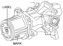
• Read out the characteristic value of the coupling component from the label or mark shown in the figure.
-
Note
-
• The 4WD control module stores the characteristic value of the coupling component before replacement.
• If the characteristic value of a new coupling component is not written, the 4WD control module does not store the value.
1. Switch the ignition ON (engine off).
2. Release the electric parking brake.
3. Switch the ignition off.
4. Disconnect the negative battery terminal. (See NEGATIVE BATTERY TERMINAL DISCONNECTION/CONNECTION.)
5. Remove the wheels and tires. (See WHEEL AND TIRE REMOVAL/INSTALLATION.)
6. Drain the rear differential oil into a container. (See DIFFERENTIAL OIL REPLACEMENT.)
7. Remove the following parts: (See FLOOR UNDER COVER REMOVAL/INSTALLATION.)
- (1) Floor under cover No.2
-
- (2) Floor under cover No.1
-
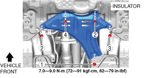
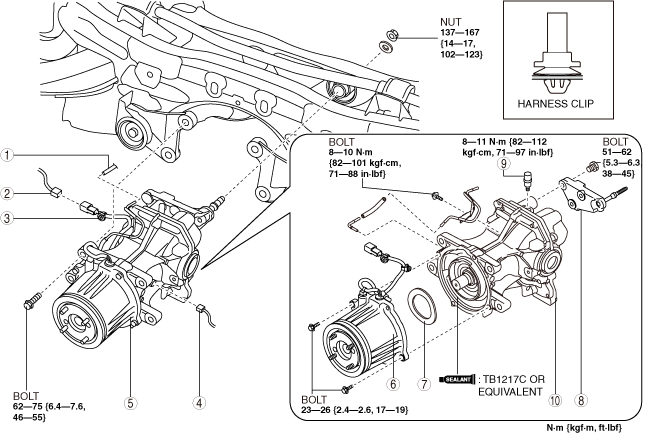
8. Remove the fasteners and bolt in the order shown in the figure.
9. Remove the insulator.
10. Remove the following parts: (See EXHAUST SYSTEM REMOVAL/INSTALLATION [SKYACTIV-D 2.2].)
- (1) Brace bar
-
- (2) Tunnel member
-
11. For SKYACTIV-D 2.2 (Without SCR system) vehicles, perform the following procedure.
- (1) Remove the middle pipe. (See EXHAUST SYSTEM REMOVAL/INSTALLATION [SKYACTIV-D 2.2].)
-
12. For SKYACTIV-D 2.2 (With SCR system) vehicles, perform the following procedure.
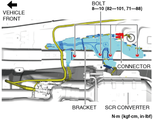
- (1) Disconnect the quick release connector from the urea injector. (See UREA INJECTOR REMOVAL/INSTALLATION [SKYACTIV-D 2.2].) (See QUICK RELEASE CONNECTOR (EMISSION SYSTEM) REMOVAL/INSTALLATION [SKYACTIV-D 2.2].)
-
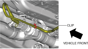
- (2) Remove the clip.
-
- (3) Remove the bolts.
-
- (4) Disconnect the connector.
-
- (5) Set the bracket aside.
-
- (6) Remove the following parts as a single unit.
-
-
• Bracket
13. Remove the propeller shaft. (See PROPELLER SHAFT REMOVAL/INSTALLATION.)
14. Remove the rear drive shaft. (See REAR DRIVE SHAFT REMOVAL/INSTALLATION.)
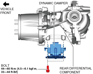
15. Remove the dynamic damper. (With dynamic damper)
16. Remove in the order indicated in the table.
17. Install in the reverse order of removal.
18. Add the specified rear differential oil. (See DIFFERENTIAL OIL REPLACEMENT.)
|
1
|
Hose
|
|
2
|
Connector (4WD solenoid)
|
|
3
|
Harness clip
|
|
4
|
Connector (differential oil temperature sensor)
|
|
5
|
Rear differential component
|
|
6
|
Coupling component
|
|
7
|
Washer
|
|
8
|
Rear differential mounting bracket
|
|
9
|
Breather
|
|
10
|
Rear differential
|
Rear Differential Component Removal Note
-
Warning
-
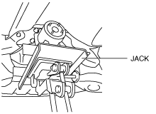
• Always verify that the rear differential component is securely supported by a jack. If the rear differential component falls off, it can cause serious injury or death, and damage to the vehicle.
1. Support the rear differential using a jack.
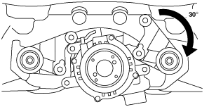
2. Loosen the differential mounting bracket bolt and rotate the bracket as shown in the figure.
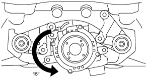
3. Rotate the rear differential as shown in the figure, and then remove the rear differential.
Rear Differential Mounting Bracket Installation Note
-
Caution
-
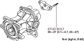
• Retighten the rear differential mounting bracket stud bolt when the rear differential mounting bracket nut is loosened.
1. Tighten the rear differential mounting bracket stud bolt.
-
Tightening torque
-
30—37 N·m {3.1—3.7 kgf·m, 23—27 ft·lbf}
 ac5uuw00000879