|
am6zzw00016728
AUTOMATIC TRANSAXLE REMOVAL/INSTALLATION [GW6A-EL (SKYACTIV-G 2.5T)]
id0517i21172i5
Replacement Part
|
washer
Quantity: 1
Location of use: plug
|
Removal
1. Disconnect the negative battery terminal. (See NEGATIVE BATTERY TERMINAL DISCONNECTION/CONNECTION.)
2. Remove the plug hole plate. (See PLUG HOLE PLATE REMOVAL/INSTALLATION [SKYACTIV-G 2.5T].)
3. Remove the following parts as a single unit. (See INTAKE-AIR SYSTEM REMOVAL/INSTALLATION [SKYACTIV-G 2.5T].)
4. Remove the battery and battery tray. (See BATTERY REMOVAL/INSTALLATION [SKYACTIV-G 2.5T].)
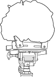
5. Disconnect the electric AT oil pump connector. (With i-stop)
am6zzw00016728
|
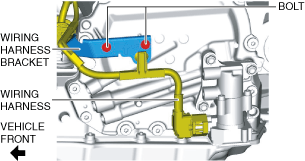
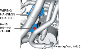
6. Remove the bolts and set the wiring harness and wiring harness bracket in a place which does not interfere with servicing. (With i-stop)
am6zzw00016729
|
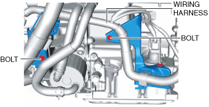
7. Remove the harness bracket installation bolts from the transaxle.
am6zzw00016730
|
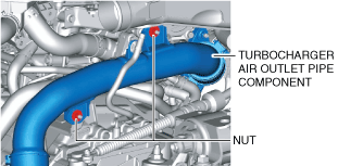
8. Remove the turbocharger air outlet pipe component installation nuts.
am6xuw00009685
|
9. Remove the EGR pipe bracket installation bolts.
am6xuw00009686
|
10. Remove the front splash shield. (See SPLASH SHIELD REMOVAL/INSTALLATION.)
11. Disconnect the control valve body connector.
am6zzw00016731
|
12. Disconnect the ground cable.
am6xuw00009687
|
13. Disconnect the selector cable from the transaxle. (See AUTOMATIC TRANSAXLE SHIFT MECHANISM REMOVAL/INSTALLATION.)
14. Remove the selector cable bracket.
am6xuw00009688
|
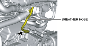
15. Disconnect the breather hose from the transaxle.
am6xuw00009689
|
16. Remove the joint cover. (See STEERING WHEEL AND COLUMN REMOVAL/INSTALLATION.)
17. Disconnect the intermediate shaft from the steering gear and linkage. (See STEERING WHEEL AND COLUMN REMOVAL/INSTALLATION.)
18. Remove the front tires. (See WHEEL AND TIRE REMOVAL/INSTALLATION.)
19. Remove the front under cover No.2. (See FRONT UNDER COVER No.2 REMOVAL/INSTALLATION.)
20. Remove the front under cover No.1. (See FRONT UNDER COVER No.1 REMOVAL/INSTALLATION.)
21. Drain the engine coolant. (See ENGINE COOLANT REPLACEMENT [SKYACTIV-G 2.5T].)
22. Drain the ATF. (See AUTOMATIC TRANSAXLE FLUID (ATF) REPLACEMENT [GW6A-EL, GW6AX-EL].)
23. Disconnect the oil cooler from the transaxle with the hose connected. (Except Automatic Transaxle Replacement) (See OIL COOLER REMOVAL/INSTALLATION [GW6A-EL (SKYACTIV-G 2.5T)].)
24. Disconnect the water hose from the oil cooler. (Automatic Transaxle Replacement) (See OIL COOLER REMOVAL/INSTALLATION [GW6A-EL (SKYACTIV-G 2.5T)].)
25. Remove the starter. (See STARTER REMOVAL/INSTALLATION [SKYACTIV-G 2.5T].)
26. Remove the blind cover.
am6xuw00009692
|
27. Hold the crankshaft pulley to prevent drive plate from rotating.
ac4ccw00002081
|
28. Remove the torque converter nuts from the starter installation hole.
am6xuw00009693
|
29. Disconnect the front ABS wheel-speed sensors from the steering knuckles. (See FRONT ABS WHEEL-SPEED SENSOR REMOVAL/INSTALLATION.)
30. Disconnect the clips securing the brake hose from the front shock absorbers. (See FRONT BRAKE HOSE REMOVAL/INSTALLATION.)
31. Disconnect the tie-rod end ball joints from the steering knuckles. (See STEERING GEAR AND LINKAGE REMOVAL/INSTALLATION.)
32. Disconnect the front lower arms from the steering knuckles. (See FRONT LOWER ARM REMOVAL/INSTALLATION.)
33. Disconnect the front stabilizer control links from the front stabilizer. (See FRONT STABILIZER REMOVAL.)
34. Disconnect the front drive shaft (LH) from the transaxle. (See FRONT DRIVE SHAFT REMOVAL/INSTALLATION.)
35. Disconnect the front drive shaft (RH) from the transaxle. (See FRONT DRIVE SHAFT REMOVAL/INSTALLATION.)
36. Remove the front crossmember component and No.1 engine mount rubber as a single unit. (See FRONT CROSSMEMBER REMOVAL/INSTALLATION.)
37. Remove the No.1 engine mounting bracket component.
am6xuw00010444
|
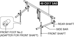
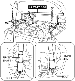
38. Install the SST using the following procedures.
ac5wzw00004302
|
am6xuw00010445
|
am6xuw00010446
|
am6xuw00010447
|
am6xuw00010448
|
Engine front side
am6xuw00010449
|
Engine rear side
am6xuw00010450
|
am6xuw00010451
|
am6xuw00010452
|
am6xuw00010453
|
am6xuw00010454
|
39. Remove in the order shown in the figure.
am6xuw00009694
|
|
1
|
Transaxle mounting bolts (upper side)
|
|
2
|
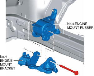
No.4 engine mount bracket
|
|
3
|
Transaxle mounting bolts (lower side)
|
|
4
|
Transaxle
|
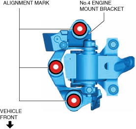
No.4 engine mount bracket removal note
1. Place alignment marks on the locations shown in the figure so that they can be assembled to the same positions as before removal.
am6xuw00009695
|
2. Remove the No.4 engine mount bracket.
Transaxle mounting bolt removal note
1. Adjust the SST and lean the engine toward the transaxle.
am6xuw00010453
|
2. Support the transaxle on a jack.
ac5wzw00004314
|
3. Remove the transaxle mounting bolts (lower side).
4. Remove the transaxle.
Installation
1. If the transaxle is replaced with a new one, perform the following procedure.
ac9uuw00011693
|
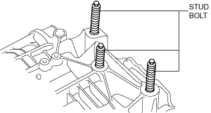
2. Verify that the torque converter stud bolts are inserted into the drive plate bolt holes from the starter installation hole.
am6xuw00009696
|
3. Install the transaxle mounting bolts.
ac5wzw00004316
|
4. Tighten the stud bolts for the transaxle.
ac5wzw00004317
|
5. Install the No.4 engine mount bracket to No.4 engine mount rubber, and temporarily tighten the installation bolt.
am6xuw00009697
|
6. Pull up the transaxle using the SSTs, pass the transaxle stud bolts through the No.4 engine mount bracket, and temporarily tighten the No.4 engine mount installation nuts.
am6xuw00010455
|
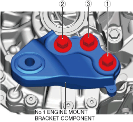
7. Install the No.1 engine mount bracket component, and tighten the installation bolts in the order shown in the figure.
am6xuw00010456
|
8. Install the front crossmember component and No.1 engine mount rubber as a single unit. (See FRONT CROSSMEMBER REMOVAL/INSTALLATION.)
9. Temporarily tighten the No.1 engine mount rubber installation bolts.
am6xuw00010457
|
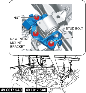
10. Align the positions of the No.4 engine mount bracket installation nuts with the No.4 engine mount bracket.
am6xuw00010458
|
11. Tighten the No.4 engine mount bracket installation nuts and bolt in the order shown in the figure.
am6xuw00010459
|
|
No. |
Tightening torque |
|---|---|
|
1, 2, 3
|
92—116 N·m {9.4—11 kgf·m, 69—85 ft·lbf}
|
|
4
|
81—99 N·m {8.3—10 kgf·m, 60—73 ft·lbf}
|
12. Tighten the No.1 engine mount rubber installation bolts in the order shown in the figure.
am6xuw00010460
|
|
No. |
Tightening torque |
|---|---|
|
1
|
141—172 N·m {15—17 kgf·m, 104—126 ft·lbf}
|
|
2
|
130—164 N·m {14—16 kgf·m, 96—120 ft·lbf}
|
13. Remove the SSTs.
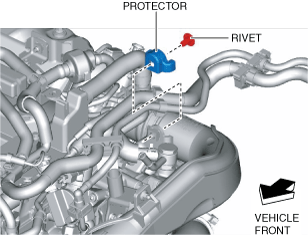
14. Install the protector.
am6xuw00010448
|
15. Connect the clip shown in the figure to the protector.
am6xuw00010447
|
16. Install the bolts and clip shown in the figure.
am6xuw00010461
|
17. Fix the crankshaft pulley to lock the torque converter against rotation.
ac4ccw00002081
|
18. Tighten the torque converter installation nut.
am6xuw00009693
|
19. Install the blind cover.
am6xuw00009692
|
20. Install the starter. (See STARTER REMOVAL/INSTALLATION [SKYACTIV-G 2.5T].)
21. Connect the front drive shaft (RH) to the transaxle. (See FRONT DRIVE SHAFT REMOVAL/INSTALLATION.)
22. Connect the front drive shaft (LH) to the transaxle. (See FRONT DRIVE SHAFT REMOVAL/INSTALLATION.)
23. Connect the front stabilizer control links to the front stabilizer. (See FRONT STABILIZER INSTALLATION.)
24. Connect the front lower arms to the steering knuckles. (See FRONT LOWER ARM REMOVAL/INSTALLATION.)
25. Connect the tie-rod end ball joints to the steering knuckles. (See STEERING GEAR AND LINKAGE REMOVAL/INSTALLATION.)
26. Connect the clips securing the brake hose to the front shock absorbers. (See FRONT BRAKE HOSE REMOVAL/INSTALLATION.)
27. Connect the front ABS wheel-speed sensors to the steering knuckles. (See FRONT ABS WHEEL-SPEED SENSOR REMOVAL/INSTALLATION.)
28. Connect the water hose to the oil cooler. (Automatic Transaxle Replacement) (See OIL COOLER REMOVAL/INSTALLATION [GW6A-EL (SKYACTIV-G 2.5T)].)
29. Connect the oil cooler to the transaxle with the hose connected. (Except Automatic Transaxle Replacement) (See OIL COOLER REMOVAL/INSTALLATION [GW6A-EL (SKYACTIV-G 2.5T)].)
30. Install the front under cover No.1. (See FRONT UNDER COVER No.1 REMOVAL/INSTALLATION.)
31. Install the front under cover No.2. (See FRONT UNDER COVER No.2 REMOVAL/INSTALLATION.)
32. Install the front tires. (See WHEEL AND TIRE REMOVAL/INSTALLATION.)
33. Install the intermediate shaft to the steering gear and linkage. (See STEERING WHEEL AND COLUMN REMOVAL/INSTALLATION.)
34. Install the joint cover. (See STEERING WHEEL AND COLUMN REMOVAL/INSTALLATION.)
35. Connect the breather hose to the transaxle.
am6xuw00009689
|
36. Install the selector cable bracket.
am6xuw00009699
|
37. Connect the selector cable to the transaxle. (See AUTOMATIC TRANSAXLE SHIFT MECHANISM REMOVAL/INSTALLATION.)
38. Connect the ground cable as shown in the figure.
am6xuw00009700
|
39. Connect the control valve body connector.
am6zzw00016731
|
40. Install the front splash shield. (See SPLASH SHIELD REMOVAL/INSTALLATION.)
41. Install the EGR pipe bracket installation bolts.
am6xuw00009701
|
42. Install the turbocharger air outlet pipe component installation nuts.
am6xuw00009702
|
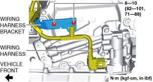
43. Install the wiring harness bracket.
am6zzw00016732
|
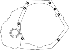
44. Tighten the wiring harness bracket installation bolts in the order shown in the figure.
am6zzw00016733
|
45. Install the wiring harness bracket. (With i-stop)
am6zzw00016734
|
46. Connect the electric AT oil pump connector. (With i-stop)
am6zzw00016728
|
47. Install the battery and battery tray. (See BATTERY REMOVAL/INSTALLATION [SKYACTIV-G 2.5T].)
48. Install the following parts as a single unit. (See INTAKE-AIR SYSTEM REMOVAL/INSTALLATION [SKYACTIV-G 2.5T].)
49. Install the plug hole plate. (See PLUG HOLE PLATE REMOVAL/INSTALLATION [SKYACTIV-G 2.5T].)
50. Connect the negative battery terminal. (See NEGATIVE BATTERY TERMINAL DISCONNECTION/CONNECTION.)
51. Refill the engine coolant. (See ENGINE COOLANT REPLACEMENT [SKYACTIV-G 2.5T].)
52. Add the ATF. (See AUTOMATIC TRANSAXLE FLUID (ATF) REPLACEMENT [GW6A-EL, GW6AX-EL].)
53. Perform the “TCM configuration”. (automatic transaxle replacement). (See TCM CONFIGURATION [GW6A-EL, GW6AX-EL].)
54. Perform the “Initial Learning” (automatic transaxle replacement). (See INITIAL LEARNING [GW6A-EL, GW6AX-EL].)
55. Perform the “Mechanical System Test”. (See MECHANICAL SYSTEM TEST [GW6A-EL, GW6AX-EL].)