STEERING SHAFT INSPECTION


id061300801600

1.  Disconnect the negative battery terminal. (See NEGATIVE BATTERY TERMINAL DISCONNECTION/CONNECTION.)

2.  Remove the following parts:

(1)  Driver-side front scuff plate (See FRONT SCUFF PLATE REMOVAL/INSTALLATION.)
(2)  Driver-side front side trim (See FRONT SIDE TRIM REMOVAL/INSTALLATION.)
(3)  Bonnet release lever (See BONNET LATCH AND RELEASE LEVER REMOVAL/INSTALLATION.)
(4)  Fuel-filler lid opener lever (See FUEL-FILLER LID OPENER AND LEVER REMOVAL/INSTALLATION.)
(5)  Driver-side decoration panel (See DECORATION PANEL REMOVAL/INSTALLATION.)
(6)  Driver-side lower panel (See LOWER PANEL REMOVAL/INSTALLATION.)

3.  Inspect the steering column for excessive play and damage.

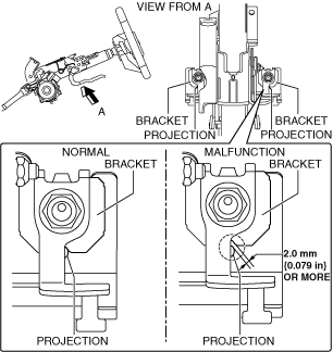
4.  Verify that the clearance between the projection on the steering column shown in the figure and the bracket is less than 2.0 mm {0.079 in}.

ac5uuw00006378

•  If the clearance between the projection and bracket is 2.0 mm {0.079 in} or more, replace the steering column component. (See STEERING WHEEL AND COLUMN REMOVAL/INSTALLATION.)
Note
•  If the clearance between the projection and bracket is 2.0 mm {0.079 in} or more, the impact absorbing mechanism of the steering column will operate, therefore it is necessary to replace the steering column component.