 |
am6zzw00017604
AIR INTAKE ACTUATOR INSPECTION
id074000801500
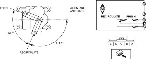
L.H.D.:
1. Disconnect the negative battery cable. (See NEGATIVE BATTERY TERMINAL DISCONNECTION/CONNECTION.)
2. Remove the following parts:
3. Remove the air intake actuator. (See AIR INTAKE ACTUATOR REMOVAL/INSTALLATION.)
4. Apply battery positive voltage and connect the ground to the air intake actuator terminals as indicated in the table below and verify the operation condition.
|
B+ Terminal |
Ground Terminal |
Operation |
|---|---|---|
|
B
|
A
|
FRESH → RECIRCULATE
|
|
A
|
B
|
RECIRCULATE → FRESH
|
am6zzw00017604
|
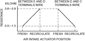
5. Verify that the resistance between terminals C and D, D and E matches the air intake actuator operation as shown in the graph.
am6xuw00012225
|
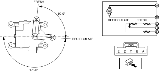
R.H.D.:
1. Disconnect the negative battery cable. (See NEGATIVE BATTERY TERMINAL DISCONNECTION/CONNECTION.)
2. Remove the following parts:
3. Remove the air intake actuator. (See AIR INTAKE ACTUATOR REMOVAL/INSTALLATION.)
4. Apply battery positive voltage and connect the ground to the air intake actuator terminals as indicated in the table below and verify the operation condition.
|
B+ Terminal |
Ground Terminal |
Operation |
|---|---|---|
|
A
|
B
|
FRESH → RECIRCULATE
|
|
B
|
A
|
RECIRCULATE → FRESH
|
am6zzw00017605
|
5. Verify that the resistance between terminals E and D, D and C matches the air intake actuator operation as shown in the graph.
am6zzw00015910
|