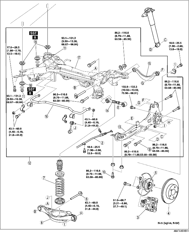
REAR CROSSMEMBER REMOVAL/INSTALLATION
id021400801000
-
Caution
-
• Performing the following procedures without first removing the ABS wheel-speed sensor may possibly cause an open circuit in the harness if it is pulled by mistake. Before performing the following procedures, remove the ABS wheel-speed sensor (axle side) and fix it to an appropriate place where the sensor will not be pulled by mistake while servicing the vehicle.
1. Remove the rear auto leveling sensor and harness.
(See REAR AUTO LEVELING SENSOR REMOVAL/INSTALLATION.)
2. Remove the middle pipe.
(See EXHAUST SYSTEM REMOVAL/INSTALLATION [LF, L3].)
3. Remove in the order indicated in the table.
4. Install in the reverse order of removal.
5. Adjust the headlight zeroset.
(See HEADLIGHT ZEROSET.)
6. Inspect the rear wheel alignment.
(See REAR WHEEL ALIGNMENT.)
|
1
|
ABS wheel-speed sensor
|
|
2
|
Parking brake cable
|
|
3
|
Caliper component
|
|
4
|
Disc plate
|
|
5
|
Spindle and hub component
|
|
6
|
Bolt (stabilizer control link)
|
|
7
|
Rear coil spring
|
|
8
|
Rear lower arm
|
|
9
|
Bolt (rear shock absorber lower side)
|
|
10
|
Bolt (trailing link front side)
|
|
11
|
Nut (crossmember)
|
|
12
|
Crossmember component
|
|
13
|
Trailing link
|
|
14
|
Rear lateral link
|
|
15
|
Rear upper arm
|
|
16
|
Rear stabilizer
|
|
17
|
Rear crossmember
|
|
18
|
Rear crossmember Bushing
|
Caliper Component Removal Note
1. Remove the caliper, and suspend it aside with cable.
Bolt (Trailing Link Front Side) Removal Note
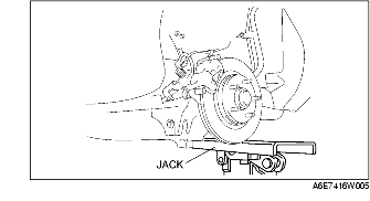
1. Support the trailing link with a jack.
2. Loosen the bolt (lateral link inner side).
Crossmember Component Removal Note
-
Warning
-
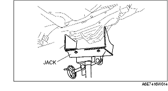
• Removing the crossmember is dangerous. The crossmember component could fall and cause serious injury or death. Verify that the jack securely supports the crossmember component.
1. Support the crossmember component using a jack and remove the nuts.
2. Remove the crossmember component.
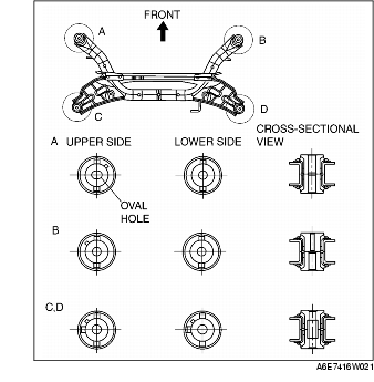
Rear Crossmember Bushing Removal Note
1. Remove the bushing using screw driver (-), being care not to damage the rear crossmember.
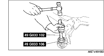
Rear Crossmember Bushing Installation Note
1. Set the bushings as shown in the figure.
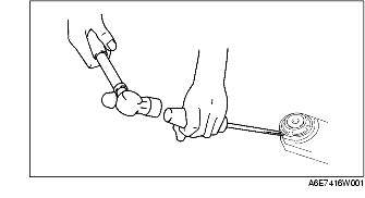
2. Tap the bushing onto the rear crossmember using the SSTs.
Bolt (Trailing Link Front Side) Installation Note
1. Support the trailing link with a jack.
2. Tighten the bolts (trailing link front side).