1. Disconnect the negative battery cable.
2. Remove the battery and battery tray.
3. Remove the air cleaner component. (See INTAKE-AIR SYSTEM REMOVAL/INSTALLATION [LF, L3].)
4. Remove the front tires and splash shield.
5. Remove the under cover.
6. Remove the steering gear and power steering pipe. (See STEERING GEAR AND LINKAGE REMOVAL/INSTALLATION.)
7. Remove the front auto leveling sensor. (See FRONT AUTO LEVELING SENSOR REMOVAL/INSTALLATION.)
8. Drain the ATF. (See AUTOMATIC TRANSAXLE FLUID (ATF) REPLACEMENT [FN4A-EL].)
Warning
9. Remove in the order shown in the figure.
10. Install in the reverse order of removal.
11. Adjust the headlight zeroset. (See HEADLIGHT ZEROSET.)
12. Add ATF to the specified level. (See AUTOMATIC TRANSAXLE FLUID (ATF) REPLACEMENT [FN4A-EL].)
13. Carry out the mechanical system test. (See MECHANICAL SYSTEM TEST [FN4A-EL].)
|
Service item
|
Test item
|
||
|---|---|---|---|
|
Line pressure test
|
Stall test
|
Time lag test
|
|
|
ATX replacement
|
X
|
|
|
|
ATX overhaul
|
X
|
X
|
X
|
|
Torque converter replacement
|
X
|
X
|
|
|
Oil pump replacement
|
X
|
|
|
|
Clutch system replacement
|
X
|
|
X
|
Test to be performed after the service work
14. Carry out the road test. (See ROAD TEST [FN4A-EL].)
.
|
1
|
Heated oxygen sensor connector
|
|
2
|
Oil pressure switch connector (for oil filter)
|
|
3
|
Oil pressure switch connector (for ATX)
|
|
4
|
Input/turbine speed sensor connector
|
|
5
|
TR switch connector
|
|
6
|
Transaxle connector
|
|
7
|
VSS connector (Without ABS)
|
|
8
|
Oil dipstick and filler tube
|
|
9
|
Harness bracket
|
|
10
|
Oil hose
|
|
11
|
Selector cable
|
|
12
|
Transaxle mounting bolt (Upper side)
|
|
13
|
Starter
|
|
14
|
Endplate cover
|
|
15
|
Tie-rod end ball joint
|
|
16
|
Stabilizer control link
|
|
17
|
Damper fork
|
|
18
|
Lower arm (front, rear) ball joint
|
|
19
|
Drive shaft
|
|
20
|
Drive shaft
|
|
21
|
Joint shaft
|
|
22
|
No.1 engine mount
|
|
23
|
Crossmember bracket
|
|
24
|
Crossmember (See FRONT CROSSMEMBER REMOVAL/INSTALLATION.)
|
|
25
|
Torque converter installation nuts (See Torque Converter Nuts Removal Note.) (See Torque Converter Nuts Installation Note.)
|
|
26
|
No.4 engine mount
|
|
27
|
Transaxle mounting bolt (lower side)
|
|
28
|
Transaxle (See Transaxle Removal Note)(Transaxle Installation Note.)
|
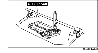
1. Support the engine using the SST before removing the No.1 engine mount.
2. Remove the No.1 engine mount.
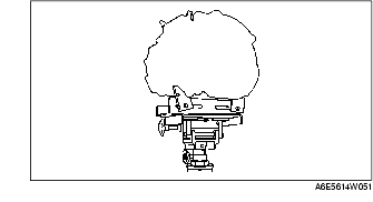
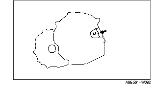
1. Loosen the part marked A and lean the engine toward the transaxle.
2. Support the transaxle on a jack.
3. Remove the transaxle mounting bolts.
4. Remove the transaxle.
1. Set the transaxle on a jack and lift it.
2. Install the transaxle mounting bolts.
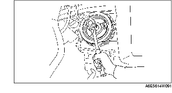
1. Hold the crankshaft pulley to prevent drive plate from rotating.
2. Remove the torque converter nuts from the starter installation hole.
1. Hold the crankshaft pulley to prevent drive plate from rotating.
2. Tighten the torque converter mounting nuts.
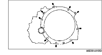
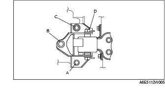
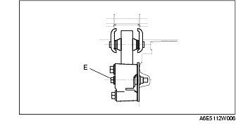
1. Verify that the engine mount rubbers are installed as shown.
2. By aligning the holes with the stud bolts, install the No.4 engine mount bracket to the transaxle.
3. By aligning the holes with the stud bolts, install the No.1 engine mount to the transaxle.
4. Align the hole of the No.4 engine mount bracket with the No.4 engine mount rubber on vehicle, and temporarily tighten the bolt D.
5. Tighten the nut B,C in order of B→C, then bolt A.
6. Tighten the bolt D.
7. Tighten the bolt D to the No.1 engine mount.
8. Remove the SST (49 E017 5A0).