ENGINE DISASSEMBLY/ASSEMBLY [L8, LF, L5]
id0110a6800500
-
Caution
-
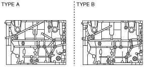
L5
• If the crankshaft and the cylinder block are replaced with a type B from a type A as shown in the figure, perform PCM reprogramming. Otherwise, the engine could be damaged. (See
PCM REPROGRAMMING [L8, LF, L5].)
Crankshaft
Cylinder block
1. Remove the joint shaft. (See JOINT SHAFT REMOVAL/INSTALLATION.)
2. Remove the engine from the transaxle. (See AUTOMATIC TRANSAXLE REMOVAL/INSTALLATION [FS5A-EL] (ATX).) (See MANUAL TRANSAXLE REMOVAL/INSTALLATION [G35M-R] (5MTX).) (See MANUAL TRANSAXLE REMOVAL/INSTALLATION [G66M-R] (6MTX).)
3. Remove the generator. (See GENERATOR REMOVAL/INSTALLATION [L8, LF, L5].)
4. Remove the exhaust system. (See EXHAUST SYSTEM REMOVAL/INSTALLATION [L8, LF, L5].)
5. Remove the EGR valve. (See EGR VALVE REMOVAL/INSTALLATION [L8, LF, L5].)
6. Remove the intake-air system. (See INTAKE-AIR SYSTEM REMOVAL/INSTALLATION [L8, LF, L5].)
7. Remove the fuel injectors. (See FUEL INJECTOR REMOVAL/INSTALLATION [L8, LF, L5].)
8. Remove the ignition coils. (See IGNITION COIL REMOVAL/INSTALLATION [L8, LF, L5].)
9. Remove the crankshaft position (CKP) sensor. (See CRANKSHAFT POSITION (CKP) SENSOR REMOVAL/INSTALLATION [L8, LF, L5].)
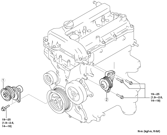
10. Remove in the order indicated in the table.
11. Assemble in the reverse order of disassembly.
|
1
|
Drive belt auto tensioner
|
|
2
|
Drive belt idler pulley
|