am6zzw00001304
|
SOLENOID VALVE INSPECTION (PRIMARY CONTROL VALVE BODY) [FS5A-EL]
id051721807700
On-Vehicle Inspection
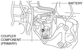
1. Disconnect the coupler component connector (primary).
am6zzw00001304
|
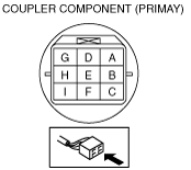
2. Measure the resistance between the following terminals.
am6zzw00000336
|
|
Solenoid valve |
Terminal |
Resistance (ohm) |
|---|---|---|
|
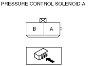
Pressure control solenoid A
|
D—I
|
2.4—7.3
|
|
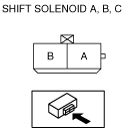
Shift solenoid A
|
A—GND
|
1.0—4.2
|
|
Shift solenoid B
|
C—GND
|
1.0—4.2
|
|
Shift solenoid C
|
G—GND
|
1.0—4.2
|
|
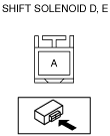
Shift solenoid D
|
B—GND
|
10.9—26.2
|
|
Shift solenoid E
|
F—GND
|
10.9—26.2
|
Off‐Vehicle Inspection
1. Disconnect the negative battery cable
2. Remove the solenoid valve. (See SOLENOID VALVE REMOVAL/INSTALLATION (PRIMARY CONTROL VALVE BODY) [FS5A-EL].)
3. Measure the resistance of each solenoid valve individually.
am6zzw00002722
|
am2zzw00000992
|
am2zzw00000993
|
Operating Inspection
1. Disconnect the coupler component connector (primary).
am6zzw00001304
|
2. Apply battery positive voltage to terminals A, B, C, F or G and battery negative voltage to GND, and verify that operating sound is heard from solenoid.
am6zzw00000336
|
3. Apply battery positive voltage to terminal D and battery negative voltage to terminal I, and verify that operating sound is heard from solenoid.