 |
am6zzw00001188
ELECTRIC POWER STEERING (EPS) ON-BOARD DIAGNOSIS
id060200813500
On-Board Diagnostic (OBD) Test Description
Read/clear diagnostic results
PID/Data monitor and record
Active command modes
Reading DTCs Procedure
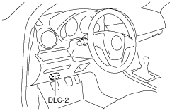
1. Connect the M-MDS to the DLC-2.
am6zzw00001188
|
2. After the vehicle is identified, select the following items from the initialization screen of the M-MDS.
3. Verify the DTC according to the directions on the screen.
4. After completion of repairs, clear all DTCs stored in the EPS. (See Clearing DTCs Procedures.)
Clearing DTCs Procedures
1. Connect the M-MDS to the DLC-2.
am6zzw00001188
|
2. After the vehicle is identified, select the following items from the initialization screen of the M-MDS.
3. Verify the DTC according to the directions on the screen.
4. Press the clear button on the DTC screen to clear the DTC.
5. Switch the ignition to off.
6. Switch the ignition to ON and wait for 5 s or more.
7. Press the retest button on the DTC screen.
8. Verify that no DTCs are displayed.
PID/Data Monitor and Record Procedure
1. Connect the M-MDS to the DLC-2.
am6zzw00001188
|
2. After the vehicle is identified, select the following items from the initialization screen of the M-MDS.
3. Select the applicable PID from the PID table.
4. Verify the PID data according to the directions on the screen.
Active Command Modes Procedure
1. Connect the M-MDS to the DLC-2.
am6zzw00001188
|
2. After the vehicle is identified, select the following items from the initialization screen of the M-MDS.
3. Select the active command modes from the PID table.
4. Perform the active command modes, inspect the operations for each parts.
DTC Table
|
DTC |
Diagnosis system component |
Page |
|---|---|---|
|
M-MDS |
||
|
C200B:1C
|
Torque sensor
|
(See DTC C200B:1C/C200B:1E.)
|
|
C200B:1E
|
Torque sensor
|
(See DTC C200B:1C/C200B:1E.)
|
|
C200B:25
|
Torque sensor
|
(See DTC C200B:25/C200B:62.)
|
|
C200B:54
|
EPS system (neutral position setting not performed)
|
(See DTC C200B:54.)
|
|
C200B:62
|
Torque sensor
|
(See DTC C200B:25/C200B:62.)
|
|
C200D:1C
|
Resolver sensor
|
(See DTC C200D:1C/C200D:62.)
|
|
C200D:62
|
Resolver sensor
|
(See DTC C200D:1C/C200D:62.)
|
|
U0001:88
|
CAN system communication error
|
(See DTC U0001:88.)
|
|
U0100:00
|
CAN system communication error
|
(See DTC U0100:00.)
|
|
U0300:00
|
EPS configuration
|
|
|
U0300:85
|
EPS configuration
|
|
|
U0401:00
|
CAN system communication error
|
(See DTC U0401:00.)
|
|
U2011:1C
|
EPS motor
|
|
|
U2011:19
|
EPS motor
|
|
|
U2011:61
|
EPS motor
|
|
|
U2011:62
|
EPS motor
|
|
|
U2011:64
|
EPS motor
|
|
|
U2011:72
|
EPS motor
|
|
|
U2100:00
|
EPS configuration
|
|
|
U3000:16
|
EPS control module
|
|
|
U3000:38
|
EPS control module
|
|
|
U3000:41
|
EPS control module
|
|
|
U3000:46
|
EPS control module
|
|
|
U3000:49
|
EPS control module
|
|
|
U3000:62
|
EPS control module
|
|
|
U3000:73
|
EPS control module
|
|
|
U3000:96
|
EPS control module
|
|
|
U3000:4B
|
EPS control module
|
(See DTC U3000:4B.)
|
|
U3003:16
|
Battery power supply
|
(See DTC U3003:16/U3003:17.)
|
|
U3003:17
|
Battery power supply
|
(See DTC U3003:16/U3003:17.)
|
PID/DATA Monitor Table
|
PID name (definition) |
Unit/Operation |
Operation Status (Reference) |
Inspection item(s) |
EPS control module terminal |
|---|---|---|---|---|
|
M-MDS display |
||||
|
ENG_RPM
|
RPM
|
• Engine stopped: 0 RPM
• Engine rotating at 3,000 RPM: 3,000 RPM
|
• PCM inspection (See PCM INSPECTION [L8, LF, L5].) (See PCM INSPECTION [MZR-CD (RF Turbo)].) (See PCM INSPECTION [MZR-CD 2.2].)
|
—
|
|
MTR_CUR
|
A
|
• When not steered: Near 0 A
• Steered: Changes to positive or negative
|
• EPS control module inspection (See EPS CONTROL MODULE REMOVAL/INSTALLATION.)
|
4A, 4B, 4C
|
|
SS_TRQ1
|
Nm
|
• Not steered: Near 0 Nm
• Steered left: Changes to 0 Nm—Positive
• Steered right: Changes to 0 Nm—Negative
|
• Torque sensor inspection (See TORQUE SENSOR INSPECTION.)
|
3A, 3C, 3D
|
|
SS_TRQ2
|
Nm
|
• Not steered: Near 0 Nm
• Steered left: Changes to 0 Nm—Positive
• Steered right: Changes to 0 Nm—Negative
|
• Torque sensor inspection (See TORQUE SENSOR INSPECTION.)
|
3A, 3C, 3D
|
|
STEER_SPD
|
°/s
|
• Not steered: Near 0 °/s
• Steered: Changes according to steering speed
|
• Torque sensor inspection (See TORQUE SENSOR INSPECTION.)
|
—
|
|
VPWR
|
V
|
• Engine stopped: Approx. 12 V
• Idling: Approx. 14 V
|
• Battery inspection (See BATTERY INSPECTION [L8, LF, L5].) (See BATTERY INSPECTION [MZR-CD (RF Turbo)].) (See BATTERY INSPECTION [MZR-CD 2.2].)
• EPS control module inspection (See EPS CONTROL MODULE INSPECTION.)
• Power supply circuit inspection (ignition switch, ignition relay, fuses)
|
1B
|
|
VSPD
|
KPH, MPH
|
• Vehicle stopped: 0 KPH, 0 MPH
• Vehicle speed 20 km/h {12 mph}: 20 KPH, 12 MPH
|
• PCM inspection (See PCM INSPECTION [L8, LF, L5].) (See PCM INSPECTION [MZR-CD (RF Turbo)].) (See PCM INSPECTION [MZR-CD 2.2].)
• ABS HU/CM or DSC HU/CM inspection (See ABS HU/CM INSPECTION.) (See DSC HU/CM INSPECTION.)
|
—
|