 |
ar8uuw00002175
FUEL INJECTOR REMOVAL/INSTALLATION [13B-MSP]
id0114z2800600
1. Complete the “BEFORE SERVICE PRECAUTION”. (See BEFORE SERVICE PRECAUTION [13B-MSP].)
2. Remove the engine cover. (See ENGINE COVER REMOVAL/INSTALLATION [13B-MSP].)
3. Remove the battery cover. (See BATTERY REMOVAL/INSTALLATION [13B-MSP].)
4. Disconnect the negative battery cable. (See BATTERY REMOVAL/INSTALLATION [13B-MSP].)
5. Remove the extension manifold (upper and lower). (See INTAKE-AIR SYSTEM REMOVAL/INSTALLATION [13B-MSP].)
6. Remove the oil filler pipe. (See INTAKE-AIR SYSTEM REMOVAL/INSTALLATION [13B-MSP].)
7. Remove the metering oil pump (No.1, No.2). (See METERING OIL PUMP REMOVAL/INSTALLATION [13B-MSP].)
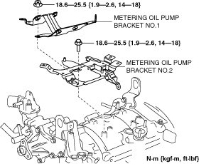
8. Remove the metering oil pump bracket (No.1, No.2). (See Metering Oil Pump Bracket No.2 Installation Note.)
ar8uuw00002175
|
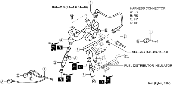
9. Remove in the order indicated in the table.
10. Install in the reverse order of removal.
11. Perform the VDI operation inspection. (See ENGINE CONTROL SYSTEM OPERATION INSPECTION [13B-MSP].)
12. Complete the “AFTER SERVICE PRECAUTION”. (See AFTER SERVICE PRECAUTION [13B-MSP].)
ar8uuw00001429
|
|
1
|
Harness connector
|
|
2
|
Fuel hose
(See Fuel Hose Installation Note.)
|
|
3
|
Fuel injector (FS, RS)
|
|
4
|
Fuel distributor (intake manifold side)
|
|
5
|
Fuel distributor (housing side)
|
|
6
|
Fuel injector (FP, RP)
|
Fuel Injector (FS, RS) Removal Note
1. Lift up the fuel distributor (intake manifold side) slightly and remove the fuel injector (intake manifold side).
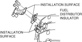
Fuel Distributor (Housing Side) Installation Note
ar8uuw00001430
|
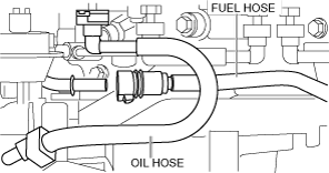
Fuel Hose Installation Note
1. Pass the fuel hose under the oil hose and install it as shown in the figure.
ar8uuw00002176
|
Harness Connector Installation Note
1. Verify the colors of the identification tape on the wiring harness connectors and the injector connections according to the following table.
Identification tape color
|
Harness Connector |
Identification tape color |
|---|---|
|
FP
|
White
|
|
RP
|
Green
|
|
FS
|
–
|
|
RS
|
–
|
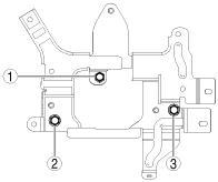
Metering Oil Pump Bracket No.2 Installation Note
1. Tighten the metering oil pump bracket No.2 installation bolts in the order shown.
ar8uuw00002177
|