FUEL TANK REMOVAL/INSTALLATION [13B-MSP]


id0114z2801600

Warning
•  A person charged with static electricity could cause a fire or explosion, resulting in death or serious injury. Before draining fuel, make sure to discharge static electricity by touching a vehicle.
•  Fuel line spills and leakage from the pressurized fuel system are dangerous. Fuel can ignite and cause serious injury or death and damage. Fuel can also irritate skin and eyes. To prevent this, always complete the "Fuel Line Safety Procedure".
Caution
•  When the fuel gauge indicates 3/4 or more, the fuel level is higher than the installation surface of the fuel pump and the fuel suction pipe bracket. Due to this condition, fuel may spill or leak out when performing this procedure. Before performing this procedure, always drain out fuel so that the fuel tank is half full or less (according to the fuel gauge needle).

1.  Park the vehicle on a level surface.

2.  Complete the “BEFORE SERVICE PRECAUTION”. (See BEFORE SERVICE PRECAUTION [13B-MSP].)

3.  Remove the rear seat. (See REAR SEAT REMOVAL/INSTALLATION.)

4.  Disconnect the quick release connector from the fuel pump unit. (See QUICK RELEASE CONNECTOR REMOVAL/INSTALLATION [13B-MSP].)

5.  Connect the hose to the fuel pump unit and drain the fuel into a container used for collecting gasoline.

6.  Drain the fuel from the fuel tank using the following procedure.

Using M-MDS
1.  Connect the M-MDS to the DLC-2
ar8uuw00001526
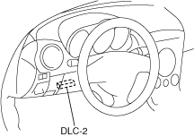
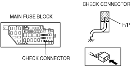
2.  Using the simulation function “FP”, start the fuel pump. (See ON-BOARD DIAGNOSTIC TEST [13B-MSP].)
Caution
•  Shorting the wrong terminal of the check connector may cause malfunctions. Make sure to short only the specified terminal.
Without using M-MDS
1.  Ground check connector terminal F/P to the body using a jumper wire.
ar8uuw00000422
Caution
•  The fuel pump may malfunction if it is operated without any fuel in the fuel tank (fuel pump idling). Constantly monitor the amount of fuel being discharged and immediately stop operation of the pump when essentially no fuel is being discharged.
2.  Turn the ignition switch to the ON position and operate the fuel pump.
Note
•  When operating the fuel pump with a full fuel tank, fuel discharge will become erratic after approx. 10 min but will continue for approx. 10 min more and then essentially no fuel will be discharged. At this time the fuel gauge needle will be at the halfway position.

7.  Stop the fuel pump using the following procedure.

Using M-MDS
1.  Using the simulation function “FP”, stop the fuel pump. (See ON-BOARD DIAGNOSTIC TEST [13B-MSP].)
Without using M-MDS
1.  Turn the ignition switch to the LOCK position and stop the fuel pump.
2.  Disconnect the jumper wire.

8.  Disconnect the negative battery cable.

9.  Remove the following parts:

(1)  Fuel pump unit. (See FUEL PUMP UNIT REMOVAL/INSTALLATION [13B-MSP].)
(2)  Main silencer and middle pipe. (See EXHAUST SYSTEM REMOVAL/INSTALLATION [13B-MSP].)
(3)  Power plant frame. (See TRANSMISSION REMOVAL/INSTALLATION [P66M-D].) (See AUTOMATIC TRANSMISSION REMOVAL/INSTALLATION [SJ6A-EL].)
(4)  Propeller shaft. (See PROPELLER SHAFT REMOVAL/INSTALLATION.)

10.  Position the parking brake cable out of the way. (See PARKING BRAKE LEVER REMOVAL/INSTALLATION.)

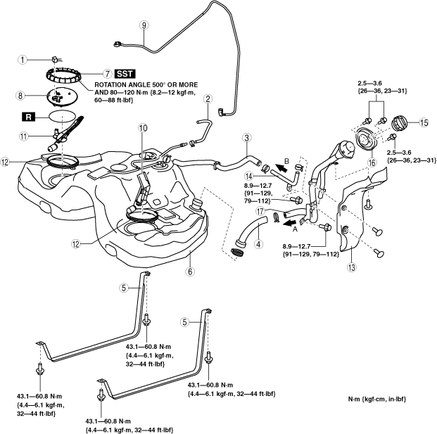
11.  Remove in the order indicated in the table.

12.  Install in the reverse order of removal.

13.  Complete the “AFTER SERVICE PRECAUTION”. (See AFTER SERVICE PRECAUTION [13B-MSP].)

ar8wzw00000875

1
Connector
2
Evaporative hose
3
Breather hose
4
Joint hose
5
Fuel tank strap
6
Fuel tank
7
Cap
8
Set plate
9
Fuel suction pipe
10
Fuel gauge sender unit (main)
11
Fuel gauge sender unit (sub)
12
Retainer
13
Protector
14
Joint pipe
15
Fuel-filler cap
16
Dust cover
17
Fuel-filler pipe


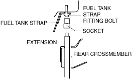
Fuel Tank Strap Removal Note

Note
•  The tool cannot reach the fitting bolt (rear) of the fuel tank strap in ways other than shown in the figure. Remove the fuel tank strap according to the following procedure.
ar8uuw00001469

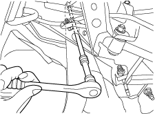
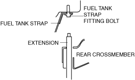
1.  Insert the extension into the service hole on the rear crossmember.

ar8uuw00001470

2.  Attach the socket to the extension in the service hole.

ar8uuw00001471

3.  Remove the fuel tank strap.
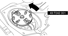

Cap Removal Note

Caution
•  The cap could be damaged if the SST is used with any play between the cap and the SST. Securely attach the SST so that there is no gap between the SST tabs and the side of the cap.

1.  Remove the cap using the SST.

ar8wzw00001569


Fuel-Filler Pipe Removal Note

1.  Remove the rear ABS wheel-speed sensor. (See REAR ABS WHEEL-SPEED SENSOR REMOVAL/INSTALLATION.)

2.  Remove the rear shock absorber lower bolt. (See REAR SHOCK ABSORBER AND COIL SPRING REMOVAL/INSTALLATION.)

3.  Remove the rear crossmember. (See REAR CROSSMEMBER REMOVAL/INSTALLATION.)

4.  Remove the fuel-filler pipe.


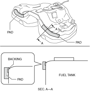
Fuel Tank Installation Note

1.  If the fuel tank is replaced with a new one, install pads to the new fuel tank as shown in the figure.

ar8uuw00003456


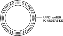
Cap Installation Note

1.  Apply water to the entire underside of the fuel pump cap.

ar8wzw00001570

Note
•  By improving the sliding of the contact surface with the fuel pump, it prevents the fuel pump from rotating together and facilitates tightening of the fuel pump cap.
•  Water is only applied to the fuel pump cap, therefore no water penetration into the tank occurs.

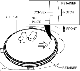
2.  Align the convex of the set plate with the notch of the retainer as shown in the figure.

ar8uuw00002455

Note
•  Remove the residue of gasoline on gasket or cap completely. Any residue of gasoline can make the set plate turn round and prevent it from fixing.

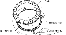
3.  Adjust the start mark of the fuel tank with the center one out of three rib lines of the cap, then turn it around 360° degrees by hand as shown in the figure.

ar8uuw00002381

•  If the retainer and cap cannot be tighten by hand, remove the cap, verify that there is no damage or misalignment on the retainer and cap, and then tighten again.
Caution
•  The cap could be damaged if the SST is used with any play between the cap and the SST. Securely attach the SST so that there is no gap between the SST tabs and the side of the cap.

4.  While keeping the alignment mark and the retainer notch aligned, tighten the cap to the rotation angle and specified torque using the SST.

•  If the specified torque cannot be obtained even when the cap is rotated to the specified rotation angle, replace with a new cap and retainer and repeat Step 3.
Rotation angle (Total angle for Step 2 and Step 3)
500° or more
Cap tightening torque (approx.)
80—120 N· m {8.2—12 kgf·m, 60—88 ft·lbf}


Joint Hose Installation Note

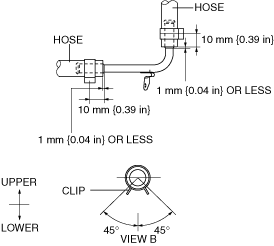
1.  Install the joint hose and clamps as shown in the figure.

ar8wzw00001571


Breather Hose Installation Note

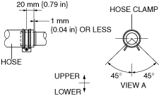
1.  Install the breather hose and clamps as shown in the figure.

ar8wzw00001572