|
ar8wzw00000209
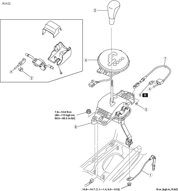
SELECTOR LEVER REMOVAL/INSTALLATION
id051400255700
1. Remove the engine cover. (See ENGINE COVER REMOVAL/INSTALLATION [13B-MSP].)
2. Remove the battery cover.
3. Disconnect the negative battery cable.
4. Remove the following parts.
5. Shift the selector lever to the P position.
6. Remove in the order indicated in the table.
7. Install in the reverse order of removal.
8. After installation, carry out the shift lock inspection and key interlock inspection.
(See SHIFT LOCK INSPECTION.)
ar8wzw00000209
|
ar8wzw00000210
|
|
1
|
Manual shaft lever component
|
|
2
|
Clip
|
|
3
|
Shift knob
|
|
4
|
Indicator component
|
|
5
|
Clip
|
|
6
|
Brake switch
|
|
7
|
Interlock cable
|
|
8
|
Selector lever
|
Manual Shaft Lever Component Removal Note
1. Mark the manual shaft lever component as shown in the figure.
ar8wzw00000211
|
2. Remove the manual shaft lever component installation nut.
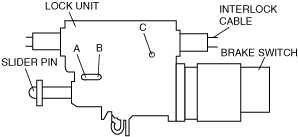
Interlock Cable Installation Note
1. Push a 1.5 mm {0.06 in}round bar or similar into hole A by fully pushing the slider pin in.
ar8wzw00000212
|
2. Push a 1.5 mm {0.06 in}round bar or similar into hole B and hole C of the lock unit until it passes through.
3. Disconnect the brake switch connector.
4. Remove the brake switch. (See BRAKE PEDAL REMOVAL/INSTALLATION.)
5. Install the new brake switch. (See BRAKE PEDAL REMOVAL/INSTALLATION.)
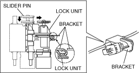
6. With the slider pin pressed, slide the lock unit to fix the lock unit hook into the bracket hole securely as shown in the figure.
ar8wzw00000213
|
7. Rotate the slider pin to release the lock, and verify that it slides freely.
8. Pull the slider pin outward until it contacts the brake pedal stopper rubber and rotate the slider pin to lock.
bhe0514w011
|
9. Verify that the shift the selector lever in P position.
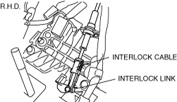
10. Install the interlock cable end to the cam pin on the selector lever.
ar8wzw00000204
|
ar8wzw00000205
|
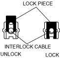
11. Fit the interlock cable in the U–groove in the selector lever base plate, and install the clip.
ar8wzw00000201
|
ar8wzw00000196
|
12. Press the interlock cable lock piece in unitl it is locked.
ar8wzw00000216
|
13. Remove a 1.5 mm {0.06 in}round bar or similar from the lock unit hole A, B and C.
ar8wzw00000212
|
14. Connect the brake switch connector with the brake pedal released.
15. Turn the ignition switch to ON position.
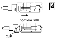
16. Install the interlock cable to the key cylinder.
17. Slide the outer casing to the key cylinder, and insert the clip over the convex part of the outer casing.
ar8wzw00000217
|
Manual Shaft Lever Component Installation Note
1. Align the mark of the manual shaft lever component as shown in the figure.
ar8wzw00000211
|
2. Install the manual shaft lever component installation nut.