 |
ar8wzw00000111
STEERING GEAR AND LINKAGE REMOVAL/INSTALLATION
id061300282100
1. Slightly bend back the front mudguard. (See FRONT MUDGUARD REMOVAL/INSTALLATION.)
2. Remove the aerodynamic under cover. (See AERODYNAMIC UNDER COVER REMOVAL/INSTALLATION.)
3. Remove the under cover. (See FRONT CROSSMEMBER REMOVAL/INSTALLATION.)
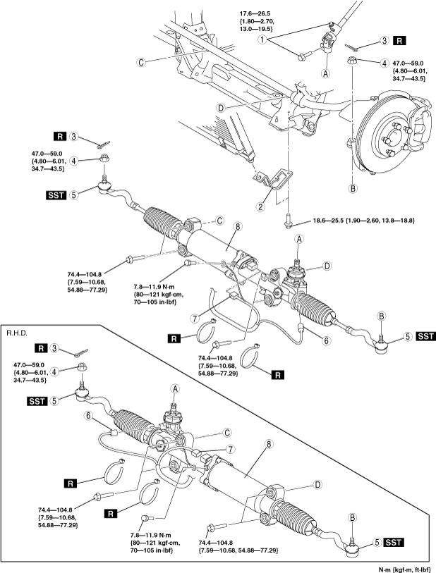
4. Remove in the order indicated in the table.
5. Install in the reverse order of removal.
6. After installation, inspect the front wheel alignment and adjust it if necessary. (See FRONT WHEEL ALIGNMENT.)
7. Set the EPS system to the neutral position. (See EPS SYSTEM NEUTRAL POSITION SETTING.)
ar8wzw00000111
|
|
1
|
Bolt (intermediate shaft)
|
|
2
|
Radiator bracket
|
|
3
|
Cotter pin
|
|
4
|
Locknut (tie-rod end)
|
|
5
|
Tie-rod end
(See Tie-rod End Removal Note.)
|
|
6
|
Torque sensor connector
|
|
7
|
EPS motor connector
|
|
8
|
Steering gear and linkage
|
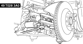
Tie-rod End Removal Note
1. Remove the outer ball joint locknut.
2. Detach the outer ball joint from the steering knuckle using the SST.
ar8wzw00000112
|
Steering Gear and Linkage Installation Note
1. Temporarily tighten the bolts.
2. Tighten the steering gear and linkage installation bolts to the specified torque in the order shown in the figure.
ar8wzw00000113
|
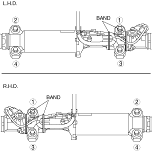
3. After connecting the connector, fix the wiring harness with the bands as shown in the figure.