ENGINE CONTROL SYSTEM OPERATION INSPECTION[L3]
id0103a4803700
Input Signal System Inspection Procedure
1. Find an irregular signal. (See Finding irregular signals.)
2. Locate source. (See Locating the source of unusual signals.)
3. Repair or replace the malfunctioning part.
4. Confirm that the irregular signal is no longer detected.
Finding irregular signals
While referring to
ON-BOARD DIAGNOSTIC TEST[L3], use the PID/DATA monitor and record function to inspect the input signal system relating to the problem.
1. Start the engine and idle the vehicle. You can assume that any signals that are out of specification by a wide margin are irregular.
2. When recreating the problem, any sudden change in monitor input signals that is not intentionally created by the driver can be determined as irregular.
Locating the source of unusual signals
-
Caution
-
• Compare the M-MDS monitor voltage with the measurement voltage using the digital measurement system function. If you use another tester, misreading may occur.
• When measuring voltage, attach the tester GND to the GND of the PCM that is being tested, or to the engine itself. If this is not performed, the measured voltage and actual voltage may differ.
• After connecting the pin to a waterproof coupler, confirming continuity and measuring the voltage, inspect the waterproof connector for cracks. If there are any, use sealant to fix them. Failure to do this may result in deterioration of the wiring harness or terminal from water damage, leading to problems with the vehicle.
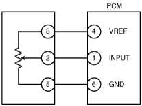
Variable resistance type 1 (TP sensor and EGR boost sensor)
Input signal system inspection for variable resistance type 1
1. When an irregular signal is detected, measure the #1 PCM terminal voltage.
-
• If the #1 terminal voltage and the M-MDS monitor voltage are the same, proceed to the next step.
• If there is a difference of 0.5 V or more, inspect for the following points concerning the PCM connector:
-
― Female terminal opening is loose.
― Coupler (pin holder) damage
― Pin discoloration (blackness)
― Harness/pin crimp is loose or disconnected.
2. Measure the #2 sensor terminal voltage.
-
• If there is a 0.5 V or more difference between the sensor and the M-MDS voltages, inspect the wiring harness for open or short circuits.
• If the sensor and the M-MDS voltages are the same, inspect for the following points concerning the sensor connector:
-
― Female terminal opening is loose.
― Coupler (pin holder) damage
― Pin discoloration (blackness)
• If there are no problems, proceed to next investigation below.
Standard power supply system inspection for variable resistance type 1
-
• Confirm that the #3 terminal is at 5 V.
-
― If the measured voltage on the #3 terminal is 5 V, inspect the following points on the sensor connector.
― If there is no problem, inspect for the following:
-
• Female terminal opening is loose.
• Coupler (pin holder) damage
• Pin discoloration (blackness)
― If the #3 terminal measures other than 5 V, inspect for the following:
-
• Open or short circuit in wiring harness
• Harness/pin crimp is loose or disconnected.
GND system inspection for variable resistance type 1
-
• Confirm that terminal sensor #5 is at 0 V.
-
― If it is at 0 V, inspect the sensor.
-
• If necessary, replace the sensor.
― If not, inspect for the following:
-
• Open or short circuit in wiring harness
• Female terminal opening is loose causing an open or short circuit in wiring harness
• Coupler (pin holder) damage
• Pin discoloration (blackness)
• Harness/pin crimp is loose or disconnected.
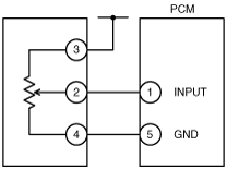
Variable resistance type 2 (mass air flow (MAF) sensor and VSS)
GND system inspection for variable resistance type 2
-
• Confirm that terminal sensor #4 is at 0 V.
-
― If it is at 0 V, inspect the sensor.
-
• If necessary, replace the sensor.
― If not at 0 V, inspect for the following:
-
• Open circuit in wiring harness
• Female terminal opening is loose.
• Coupler (pin holder) damage
• Pin discoloration (blackness)
• Harness/pin crimp is loose or disconnected.
Input signal system inspection for variable resistance type 2
1. When an irregular signal is detected, measure the #1 PCM terminal voltage.
-
• If the #1 terminal voltage and the M-MDS monitor voltage are the same, proceed to the next step.
• If there is a difference of 0.5 V or more, inspect for the following points concerning the PCM connector:
-
― Female terminal opening is loose.
― Coupler (pin holder) damage
― Pin discoloration (blackness)
― Harness/pin crimp is loose or disconnected.
2. Measure the #2 sensor terminal voltage.
-
• If there is a 0.5 V or more difference between the sensor and the M-MDS voltages, inspect the wiring harness for open or short circuits.
• If the sensor and the M-MDS voltages are the same, inspect the following points concerning the sensor connector:
-
― Female terminal opening is loose.
― Coupler (pin holder) damage
― Pin discoloration (blackness)
― Harness/pin crimp is loose or disconnected.
• If there are no problems, proceed to next investigation below.
Electrical supply system inspection for variable resistance type 2
-
• Confirm that the sensor #3 terminal is B+.
-
― If the measured voltage on the #3 terminal is B+, inspect the following points on the sensor connector.
― If there is no problem, inspect for the following:
-
• Female terminal opening is loose.
• Coupler (pin holder) damage
• Pin discoloration (blackness)
― If the #3 terminal measures other than B+, inspect the following:
-
• Open or short circuit in wiring harness
• Harness/pin crimp is loose or disconnected.
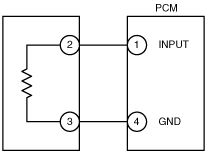
Thermistor type (IAT sensor and ECT sensor)
Input signal system inspection for thermistor type
1. When an irregular signal is detected, measure the #1 PCM terminal voltage.
-
• If the #1 terminal voltage and the M-MDS monitor voltage are the same, proceed to the next step.
• If there is a difference of 0.5 V or more, inspect the following points concerning the PCM connector:
-
― Female terminal opening loose
― Coupler (pin holder) damage
― Pin discoloration (blackness)
― Harness/pin crimp is loose or disconnected.
2. Measure the #2 sensor terminal voltage.
-
• If there is a 0.5 V or more difference between the sensor and the M-MDS voltages, inspect the wiring harness for open or short circuits.
• If the sensor and the M-MDS voltages are the same, inspect the following points concerning the sensor connector:
-
― Female terminal opening is loose.
― Coupler (pin holder) damage
― Pin discoloration (blackness)
― Harness/pin crimp is loose or disconnected.
• If there are no problems, proceed to next investigation below.
GND system inspection for thermistor type
-
• Confirm that terminal sensor #3 is at 0 V.
-
― If it is at 0 V, inspect the sensor. If necessary, replace the sensor.
― If not, inspect for the following:
-
• Open circuit in wiring harness
• Female terminal opening is loose.
• Coupler (pin holder) damage
• Pin discoloration (blackness)
• Harness/pin crimp is loose or disconnected.
Main Relay Operation Inspection
1. Verify that the main relay clicks when the ignition switch is turned to ON position and off.
-
• If there is no operation sound, inspect the following:
-
― Harness and connector between ignition switch and main relay terminal A.
― Harness and connector between PCM terminal 1AT and main relay terminal B.
Intake Manifold Vacuum Inspection
1. Verify air intake hoses are installed properly.
2. Start the engine and run it at idle.
3. Disconnect the vacuum hose between the intake manifold and purge solenoid valve from the intake manifold side.
4. Connect a vacuum gauge to the intake manifold and measure the intake manifold vacuum.
-
• If not as specified, inspect the following:
-
Specification
-
More than -70 kPa {-525 mmHg, -21 inHg}
-
Note
-
• Air suction can be located by engine speed change when lubricant is sprayed on the area where suction is occurring.
-
― Air suction at throttle body, intake manifold and PCV valve installation points
― EGR valve (stuck open)
― Fuel injector insulator
Electronic Throttle Control System Inspection
Engine coolant temperature compensation inspection
1. Connect the M-MDS to the DLC-2.
2. Access the following PIDs:
-
• ECT
• IAT
• RPM
3. Verify that the engine is cold, then start the engine.
4. Verify that the engine speed decreases as the engine warms up.
-
• If the engine speed does not decrease or decreases slowly, inspect the following:
-
― ECT sensor and related wiring harness
― Electronic throttle body and related wiring harness
Load compensation inspection
1. Start the engine and idle it.
2. Connect the M-MDS to the DLC-2.
3. Verify that P0506, P0507 is not displayed.
-
• If P0506, P0507 are displayed, perform DTC inspection.
4. Access the RPM PID.
-
Note
-
• Excludes temporary idle speed drop just after the loads are turned on.
5. Verify that the engine speed is within the specification under each load condition.
-
• If load condition is not as specified, inspect the following:
-
― A/C switch and related wiring harness
― Fan switch and related wiring harness
Engine speed
|
Load condition
|
Engine speed (rpm)*1
|
|
No load
|
650—750
|
|
E/L operating*2
|
650—750
|
|
P/S operating
|
650—750
|
|
A/C operating*3
|
650—750
|
*1 :Neutral or P position
*2 :Blower motor is operating at high speed. Headlight switch is turned on. Rear window defroster switch is turned on. Cooling fans are operating.
*3 :A/C switch and fan switch are on.
Throttle position (TP) sweep inspection
1. Connect the M-MDS to the DLC-2.
2. Turn the ignition switch to the ON position.
3. Verify that none of the following DTC are displayed:
-
• P0122, P0123, P0222, P0223, P0638, P2100, P2101, P2102, P2103, P2107, P2108, P2119, P2122, P2123, P2127, P2128, P2135, P2138
-
― If any one DTC is displayed, perform DTC inspection.
4. Access TP_REL PID.
5. Verify that the PID reading is within the CTP value. (See PCM INSPECTION[L3].)
-
• If the PID reading is out of range, perform the following:
-
― Remove the air duct from the throttle valve body.
― Verify that the throttle valve opens when the accelerator pedal is depressed.
-
• If the throttle valve opens, inspect the throttle position sensor and related wiring harness.
• If the throttle valve does not open, inspect the throttle actuator control motor and related wiring harness.
6. Gradually depress the throttle pedal and verify that the PID reading increases accordingly.
-
• If the PID reading drops momentarily, inspect the following:
-
― Throttle position sensor
7. Fully depress the throttle pedal and verify that the PID reading is within WOT value. (See PCM INSPECTION[L3].)
-
• If the PID reading is out of range, perform the followings:
-
― Remove the air duct from throttle valve body.
― Verify that the throttle valve opens when throttle pedal is depressed.
-
• If the throttle valve opens, inspect the throttle position sensor and related wiring harness.
• If the throttle valve does not open, inspect the throttle actuator control motor and related wiring harness.
Variable Intake air Control Operation Inspection [L3]
1. Start the engine.
2. Inspect the rod operation under the following condition:
Rod operation
|
Engine speed
|
4,600 rpm
|
|
Below
|
Above
|
|
Shutter valve actuator
|
Operate
|
Not operate
|
-
• If the rod operation is not as specified, inspect as follows:
- (1) Stop the engine.
-
- (2) Connect the M-MDS to the DLC-2.
-
- (3) Verify that DTC P0661 or P0662 is not displayed.
-
-
• If DTC P0661 or P0662 is shown, perform DTC inspection.
- (4) Inspect the variable intake-air solenoid valve.
- (See VARIABLE INTAKE AIR SOLENOID VALVE INSPECTION[L3].)
-
• If the variable intake-air solenoid valve is not normal, replace the variable intake-air solenoid valve.
• If the variable intake-air solenoid valve is normal, inspect the following:
-
― Vacuum hose and vacuum chamber for looseness or damage
― Shutter valve stuck open or closed
Variable Tumble Control Operation Inspection
1. Connect the M-MDS to the DLC-2.
2. Access ECT PID.
3. Verify that ECT PID is less than 63 °C {145 °F}.
4. Start the engine.
5. Inspect rod operation under the following conditions:
Rod operation
|
Engine speed
|
3,750 rpm
|
|
Below
|
Above
|
|
Shutter valve actuator
|
Operate
|
Not operate
|
-
• If the rod operation is not specified, inspect as follows:
- (1) Verify that DTC No. P2009 or P2010 is not displayed.
-
-
• If DTC No. P2009 or P2010 are shown, perform DTC inspection.
- (2) Inspect the variable tumble solenoid valve.
- (See VARIABLE TUMBLE SOLENOID VALVE INSPECTION[L3].)
-
• If the variable tumble solenoid valve is not normal, replace the variable tumble solenoid valve.
• If the variable tumble solenoid valve is normal, inspect the following:
-
― Vacuum hose and vacuum chamber for looseness or damage
― Shutter valve stuck open or closed
Fuel Injector Operation Inspection
|
STEP
|
INSPECTION
|
RESULTS
|
ACTION
|
|
1
|
While cranking the engine, inspect for fuel injector operation sound at each cylinder using a soundscope.
Is operation sound heard?
|
Yes
|
Fuel injector operation is normal.
|
|
No
|
All cylinders not heard:
Go to the next step.
Some cylinders not heard:
Go to Step 3.
|
|
2
|
Perform main relay operation inspection.
Is main relay operation normal?
|
Yes
|
Inspect the following:
• Fuel injector power system related wiring harness and connectors
• PCM connectors
• Fuel injector GND and related wiring harness and connectors
|
|
No
|
Repair or replace malfunctioning parts.
|
|
3
|
Switch fuel injector connector of not operating fuel injector with operating fuel injector.
Is operation sound heard?
|
Yes
|
Go to the next step.
|
|
No
|
Replace the fuel injector.
|
|
4
|
Are wiring harness and connectors of not operation fuel injector normal? (Open or short)
|
Yes
|
Inspect PCM terminal voltage of fuel injector signal.
|
|
No
|
Repair or replace malfunctioning parts.
|
Fuel Cut Control System Inspection
1. Warm up engine and idle it.
2. Turn off the electrical loads and A/C switch.
3. Connect the M-MDS to the DLC-2.
4. Access RPM PID.
5. Listen for the fuel injector operation sound at all cylinders using the soundscope and monitor both PIDs while performing the following steps:
- (1) Depress the accelerator pedal and increase the engine speed to 4,000 rpm.
-
- (2) Quickly release the accelerator pedal (brake pedal is not depressed) and verify that the fuel injector operation sound stops, and starts again when the engine speed drops below 1,200 rpm.
-
-
• If not as specified, inspect the following:
-
― ECT sensor and related wiring harness
― TR switch and related wiring harness
Fuel Pump Operation Inspection
1. Remove the fuel-filler cap.
2. Turn the ignition switch to the ON position.
3. Turn the fuel pump relay from off to on using the FP PID and inspect if the operation sound is heard.
-
• If no operation sounds is heard, proceed to next step.
4. Measure voltage at wiring harness side fuel pump connector terminal C (California emission regulation applicable model), A (except for California emission regulation applicable model).
-
Specification
-
B+ (Ignition switch at on)
-
• If the voltage is as specified, inspect the following:
-
― Fuel pump continuity
― Fuel pump GND
― Wiring harness between fuel pump relay and PCM terminal 1AR (with immobilizer system), 1AQ
(without immobilizer system)
• If not as specified, inspect the following:
-
― Fuel pump relay
― Wiring harness connector (Main relay—fuel pump relay—fuel pump.)
Fuel Pump Control System Inspection
1. Crank the engine and verify that fuel pump relay operation sound is heard.
2. If operation sound is not heard, inspect the following:
-
• Wiring harness and connectors (Main relay—fuel pump relay—PCM terminal 1AR (with immobilizer system), 1AQ (without immobilizer system)
Spark Test
1. Disconnect the fuel pump relay.
2. Verify that each ignition coil and connector is connected properly.
3. Inspect the ignition system in the following procedure.
-
Warning
-
• High voltage in the ignition system can cause strong electrical shock which can result in serious injury. Avoid direct contact to the vehicle body during the following spark test.
|
STEP
|
INSPECTION
|
ACTION
|
|
1
|
• Disconnect the ignition coil from the spark plugs.
• Remove the spark plugs.
• Verify that the spark plugs do not have carbon deposits.
• Are the spark plugs normal?
|
Yes
|
Go to the next step.
|
|
No
|
Perform no-load racing at 4,000 rpm for 2 min, 2 times to burn off the carbon deposits.
Repeat Step 1.
|
|
2
|
• Inspect the spark plugs for damage, wear, and proper plug gap.
• Are the spark plugs normal?
|
Yes
|
Go to the next step.
|
|
No
|
Replace spark plugs, then go to the next step.
|
|
3
|
• Reconnect the spark plugs to the ignition coil.
• Ground the spark plugs to the engine.
• Is a strong blue spark visible at each cylinder while cranking the engine?
|
Yes
|
Ignition system is normal.
|
|
No
|
Some cylinders do not spark:
• Go to the next step.
All cylinders do not spark:
• Go to Step 5.
|
|
4
|
• Inspect the following wiring harnesses for open or short:
-
― Ignition coil No.1 terminal B—PCM terminal 2BE
― Ignition coil No.2 terminal B—PCM terminal 2BF
― Ignition coil No.3 terminal B—PCM terminal 2BG
― Ignition coil No.4 terminal B—PCM terminal 2BH
• Are the wiring harnesses normal?
|
Yes
|
Inspect and replace the ignition coil.
|
|
No
|
Repair or replace the malfunctioning part, then go to Step 1.
|
|
5
|
• Measure the voltage at terminal A in each ignition coils.
• Is the voltage B+?
|
Yes
|
Go to the next step.
|
|
No
|
Inspect power supply circuit of ignition coils.
|
|
6
|
• Does the PCM connector or ignition coil connectors have poor connection?
|
Yes
|
Repair or replace the connector, then go to Step 1.
|
|
No
|
Go to the next step.
|
|
7
|
• Are the following parts normal?
-
― CKP sensor and crankshaft pulley
|
Yes
|
Inspect for open or short circuit in wiring harness and connector of CKP sensor.
|
|
No
|
Repair or replace the malfunctioning part, then go to Step 1.
|
EGR Control System Inspection
1. Crank the engine and verify that EGR valve operation (initial operation) sound is heard.
-
• If the operation sound is not heard, connect the M-MDS to the DLC-2 and verify that the DTC P0403 is shown. Perform DTC inspection. (See
DTC TABLE[L3].)
2. Start the engine and idle it.
3. Warm up the engine to normal operating temperature.
4. Access the following PIDs:
-
• ECT, RPM, SEGRP_DSD, APP1, APP2, VSS
5. Idle the vehicle and verify that the SEGRP value is 0.
6. Put the vehicle in drive.
7. Depress the accelerator pedal and verify that the SEGRP_DSD value is increased.
-
• If the EGR valve increases, inspect the following:
-
― EGR valve (stuck open or close)
― Wiring harness and connectors (Main relay—EGR valve—PCM)
• If the SEGRP_DSD value does not increase, inspect the VSS, APP1, APP2, TP and ECT PIDs. (See
PCM INSPECTION[L3].)
8. Stop the vehicle and verify that the SEGRP value returns to 0.
Purge Control System Inspection
1. Start the engine.
2. Disconnect the vacuum hose between the purge solenoid valve and the charcoal canister.
3. Put a finger to the purge solenoid valve and verify that there is no vacuum applied when the engine is cold.
-
• If there is a vacuum, inspect the following:
-
― Wiring harness and connectors (Purge solenoid valve—PCM terminal 2AN)
― Purge solenoid valve
4. Warm up the engine to the normal operating temperature.
5. Stop the engine.
6. Connect the M-MDS to the DLC-2 and verify that the DTC P0443 is shown. Perform DTC inspection. (See DTC TABLE[L3].)
7. Turn the ignition switch to the ON position.
8. Access ECT PID.
9. Verify that the engine coolant temperature is more than 78 °C {173 °F}.
-
• If the M-MDS indicates less than 78 °C {173 °F}, perform the ECT sensor inspection.
10. Set the vehicle on the dynamometer or chassis roller.
-
Warning
-
• When the dynamometer or chassis roller is operating, there is a possibility that the operator may come into contact with or be caught up in the rotating parts, leading to serious injuries or death. When performing work while the dynamometer or chassis roller is operating, be careful not to come into contact with or be caught up in any of the rotating parts.
11. Drive vehicle at engine speed approx. 2,000 rpm for 30 s or more.
12. Put a finger to the purge solenoid valve and verify that there is no vacuum applied while step 2.
-
• If there is no vacuum, inspect the following:
-
― Wiring harness and connector (Main relay—purge solenoid valve—PCM terminal 2AN)
― Purge solenoid valve
― MAF, APP1, APP2, TP and LOAD PIDs
• If there is vacuum, inspect the following:
-
― Vacuum hose (Purge solenoid valve—charcoal canister)
A/C Cut-off Control System Inspection
1. Start the engine.
2. Turn the A/C switch and the fan switch on.
3. Verify that the A/C compressor magnetic clutch actuates.
-
• If it does not actuate, go to symptom troubleshooting “No.23 A/C does not work sufficiently“.
4. Fully open the throttle valve and verify that the A/C compressor magnetic clutch does not actuate for 2—5 s.
-
• If it actuates, inspect as follows:
-
― A/C relay
― Open or short to GND circuit in wiring harness and connectors (Ignition switch—A/C relay—PCM terminal 1I)
― A/C related parts
― APP1, APP2 PIDs
Cooling Fan Control System Inspection
Cooling fan system operation
|
Engine condition
|
PCM terminal
1D
|
PCM terminal 1W
|
Cooling fan
motor No.1
|
Cooling fan
motor No.2
|
|
Cooling fan
relay No.1
|
Cooling fan
relay No.2
|
Cooling fan
relay No.3
|
|
A/C: OFF
ECT: below 100 °C [212 °F]
|
OFF
|
OFF
|
OFF
|
Stopped
|
Stopped
|
|
A/C: OFF
ECT: 100—108 °C [212—226 °F]
|
ON
|
OFF
|
OFF
|
Low speed
|
Low speed
|
|
A/C: OFF
ECT: above 108 °C [226 °F]
|
ON
|
ON
|
ON
|
High speed
|
High speed
|
|
A/C: ON (middle switch OFF)
ECT: below 108 °C [226 °F]
|
ON
|
OFF
|
OFF
|
Low speed
|
Low speed
|
|
A/C: ON (middle switch ON)
ECT: below 108 °C [226 °F]
|
ON
|
ON
|
ON
|
High speed
|
High speed
|
|
A/C: ON
ECT: above 108 °C [226 °F]
|
ON
|
ON
|
ON
|
High speed
|
High speed
|
|
ETC sensor malfunction
(PCM stores DTCs P0117 or P0118)
|
ON
|
ON
|
ON
|
High speed
|
High speed
|
1. Connect the M-MDS to DLC-2.
2. Perform the KOEO or KOER self-test. (See KOEO/KOER SELF TEST[L3].)
3. Verify that the DTC P0117, P0118, P0480 and P0481 are not displayed.
4. If the DTC P0117, P0118, P0480 or P0481 is displayed, perform DTC inspection. (See DTC TABLE[L3].)
5. Verify that the ECT PID is below 100 °C{212 °F}.
6. Turn the A/C switch to OFF.
7. Turn the ignition switch to the ON position.
8. Verify that the cooling fan and additional fan are not operating.
-
• If the cooling fan No.1 and No.2 operate low speed, inspect for following:
-
― Cooling fan relay (stuck close)
• If the cooling fan No.1 and No.2 operate high speed, inspect for following:
-
― Short to GND circuit between A/C refrigerant pressure switch and PCM terminal 1AP
• If the cooling fan No.2 operates high speed, inspect for following:
-
― Cooling fan relay No.3 (stuck)
9. Start the engine and ECT PID above 100 °C{212 °F}.
10. Verify that the cooling fan No.1 and No.2 are operating low speed.
-
• If the cooling fan No.1 and No.2 do not operate, inspect for following:
-
― Cooling fan relay No.1 (stuck open)
-
― Open circuit (battery positive post—cooling fan relay No.1—cooling fan motor No.1—cooling fan relay No.3—cooling fan motor No.2—GND.)
• If the cooling fan No.1 operates high speed, inspect for following:
-
― Cooling fan relay No.2 (stuck close)
• If the cooling fan No.2 operates high speed, inspect for following:
-
― Cooling fan relay No.3 (stuck)
• If the cooling fan No.2 does not operate, inspect for following:
-
― Cooling fan relay No.2 (stuck close)
11. Turn the ignition switch to off.
12. Disconnect the ECT sensor connector.
13. Turn the ignition switch to the ON position.
14. Verify that the cooling fan and additional fan are operating high speed.
-
• If the cooling fan No.1 does not operate, inspect for following:
-
― Cooling fan relay No.2 (stuck open)
-
― Open circuit between cooling fan relay No.2 and GND
• If the cooling fan No.2 does not operate, inspect for following:
-
― Cooling fan relay No.3 (stuck)
15. Clear the DTC P0118 from PCM memory using the M-MDS. (See AFTER REPAIR PROCEDURE[L3].)
Variable Valve Timing Control System Operation Inspection [L3]
When idling cannot be continued
1. Remove the oil control valve (OCV) and verify that the spool valve is at maximum retard position.
2. Connect the OCV.
3. Turn the ignition switch to the ON position.
4. Verify that the spool valve is at maximum retard position.
-
• If the spool valve is stuck in the advance direction, inspect for the following:
-
― Short circuit in wiring harnesses or connectors between the OCV and the PCM.
5. Inspect the variable valve timing actuator. (See VARIABLE VALVE TIMING ACTUATOR INSPECTION[L3]
When idling can be continued
1. Disconnect OCV connector.
2. Warm up the engine and idle it.
3. Apply battery voltage to the OCV and verify that the engine idles roughly or stalls.
-
• If the engine idles roughly or stalls, inspect the timing belt component (valve timing deviation).
• If the engine does not idle roughly or stalls, go to the next step.
4. Remove the OCV and perform spool valve operation inspection.
(See OIL CONTROL VALVE (OCV) INSPECTION[L3]
-
• If not as specified, inspect the following:
-
― OCV
― Harnesses and connectors between OCV and PCM open or short.
• If as specified, inspect the following hydraulic passages for clogging or leakage or both:
-
― Oil pressure switch—OCV
― OCV—camshaft
― Camshaft internal passage
5. If they are normal, replace the camshaft pulley (with built-in variable valve timing actuator).