|
1
|
VERIFY FREEZE FRAME DATA HAS BEEN RECORDED
• Has the FREEZE FRAME DATA been recorded?
|
Yes
|
Go to the next step.
|
|
No
|
Record the FREEZE FRAME DATA on the repair order, then go to the next step.
|
|
2
|
VERIFY RELATED SERVICE INFORMATION AVAILABILITY
• Verify related Service Information availability.
• Is any related Service Information available?
|
Yes
|
Perform repair or diagnosis according to the available Service Information.
• If the vehicle is not repaired, go to the next step.
|
|
No
|
Go to the next step.
|
|
3
|
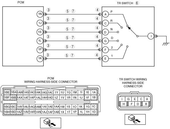
VERIFY CURRENT INPUT SIGNAL STATUS-IS CONCERN INTERMITTENT OR CONSTANT?
• Turn the ignition switch to the ON position (engine OFF).
• Inspect PCM terminal voltages.
-
― PCM terminal 1N
-
• P position: 0 V
• Other positions and all ranges: B+
― PCM terminal 1J
-
• R position: 0 V
• Other positions and all ranges: B+
― PCM terminal 1S
-
• N position: 0 V
• Other positions and all ranges: B+
― PCM terminal 1L
-
• D range: 0 V
• Other ranges and all positions: B+
― PCM terminal 1P
-
• 2 range: 0 V
• Other ranges and all positions: B+
― PCM terminal 1K
-
• 1 range: 0 V
• Other ranges and all position: B+
• Are two or more of following terminal voltage at the same time when shifting selector lever from P position to 1 range?
|
Yes
|
Go to the next step.
|
|
No
|
Go to intermittent concern troubleshooting procedure.
|
|
4
|
INSPECT TR SWITCH CONNECTOR
• Turn the ignition switch to the LOCK position.
• Disconnect the TR switch connector.
• Inspect for bent terminals of pins using mirror.
• Are TR switch terminals normal?
|
Yes
|
Go to the next step.
|
|
No
|
Repair the terminals or replace the TR switch, then go to Step 8.
|
|
5
|
INSPECT TR SWITCH CIRCUIT MALFUNCTION
• Turn the ignition switch to the ON position (engine OFF).
• Does PCM terminal voltage change from B+ to 0 V when TR switch connector is disconnected?
|
Yes
|
Go to the next step.
|
|
No
|
Go to Step 7.
|
|
6
|
INSPECT TR SWITCH CONTINUITY
• Turn the ignition switch to the LOCK position.
• Disconnect the TR switch connector.
• Inspect TR switch for continuity in positions/ranges failed in Step 4.
• Is there continuity between TR switch terminals (part side)?
|
Yes
|
Go to Step 8.
|
|
No
|
Replace the TR switch, then go to Step 8.
|
|
7
|
INSPECT TR SWITCH CIRCUIT FOR SHORT TO GROUND
• Inspect for continuity between PCM terminals (wiring harness-side) and body ground.
-
― PCM terminal: 1J, 1K, 1L, 1N, 1P, 1S
• Is there continuity?
|
Yes
|
Repair or replace the wiring harness, then go to the next step.
|
|
No
|
Go to the next step.
|
|
8
|
VERIFY TROUBLESHOOTING OF DTC P0705 COMPLETED
• Make sure to reconnect all disconnected connectors.
• Clear DTC from memory using M-MDS.
• Drive vehicle in each range (P, R, N, D, 2, and 1) for 100 s or more.
• Is same DTC present?
|
Yes
|
Replace the PCM, then go to the next step.
|
|
No
|
Go to the next step.
|
|
9
|
VERIFY AFTER REPAIR PROCEDURE
• Perform "After Repair Procedure".
• Is there any DTC present?
|
Yes
|
Go to the applicable DTC inspection.
|
|
No
|
DTC troubleshooting completed.
|