ENGINE CONTROL SYSTEM OPERATION INSPECTION [AJ (3.0L Duratec)]
id0103a7803700
Main Relay Operation Inspection
1. Verify the main relay clicks when the ignition switch is turned to ON position and off.
-
• If there is no operation sound, inspect then followings.
-
• Main relay (See RELAY INSPECTION.)
-
• Harness and connector between the ignition switch and main relay terminal E (R.H.D.).
-
• Harness and connector between the main relay terminal A and GND (R.H.D.).
-
• Harness and connector between the ignition switch and main relay terminal A (L.H.D.).
-
• Harness and connector between the main relay terminal B and GND (L.H.D.).
Intake Manifold Vacuum Inspection
1. Verify air intake hoses are installed properly.
2. Start the engine and run it at idle.
3. Measure the manifold vacuum using a vacuum gauge.
-
• If not as specified, inspect following.
-
- Air suction at throttle body, intake manifold and PCV valve installation points
-
- Accelerator cable free play
-
- Fuel injector insulator
-
- Engine compression
-
Specification
-
Above 60 kPa {450 mmHg, 18 inHg}
Idle Air Control Inspection
Engine coolant temperature compensation inspection
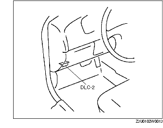
1. Connect the SSTs (WDS or equivalent) to DLC-2.
2. Select the PID/DATA MONITOR AND RECORD function on the WDS or equivalent display.
3. Select the following PIDs.
-
• ECT
-
• RPM
4. Verify that the engine is in cold condition, then start the engine.
5. Verify that the engine speed decreases as the engine warms up.
-
• If the engine speed does not decrease or decreases slowly, inspect the following.
-
- ECT sensor and related harness (See ENGINE COOLANT TEMPERATURE (ECT) SENSOR INSPECTION [AJ (3.0L Duratec)].)
-
- IAC valve and related harness (See IDLE AIR CONTROL (IAC) VALVE INSPECTION [AJ (3.0L Duratec)].)
Fuel Injector Operation Inspection
|
STEP
|
INSPECTION
|
ACTION
|
|
1
|
• While cranking engine, inspect for fuel injector operation sound at each cylinder using a soundscope.
• Is operation sound heard?
|
Yes
|
Fuel injector operation is okay.
|
|
No
|
All cylinders no heard:
• Go to the next step.
Some cylinders no heard:
• Go to step 3.
|
|
2
|
• Carry out main relay operation inspection.
• Is main relay operation normal?
|
Yes
|
Inspect following.
• Fuel injector power system related wiring harness and connectors
• PCM connectors
• Fuel injector GND and related wiring harness and connectors
|
|
No
|
Repair or replace malfunctioning part.
|
|
3
|
• Change fuel injector connector of not operating fuel injector and operating fuel injector.
• Is operation sound heard?
|
Yes
|
Go to the next step.
|
|
No
|
Replace fuel injector.
|
|
4
|
• Are wiring harness and connectors of not operating fuel injector okay? (Open or short)
|
Yes
|
Inspect PCM terminal voltage of fuel injector signal.
|
|
No
|
Repair or replace malfunctioning part.
|
Fuel Cut Control System Inspection
1. Warn up the engine and let it idle.
2. Turn off the electrical loads and A/C switch.
3. Connect the WDS or equivalent to DLC-2.
4. Select RPM, FUELPW1 and FUELPW2 PIDs.
5. Monitor both PIDs while performing the following steps.
-
(1) Depress the accelerator pedal and increase the engine speed to 4,000 rpm.
-
(2) Release the accelerator pedal (brake pedal is not depressed) and verify that the fuel injector duration time (FUELPW1 and FUELPW2 PIDs) is 0 msec., and 2-5 msec. When the engine speed drops below 1,200 rpm.
-
• If not as specified, inspect the following.
-
- ECT sensor and related harness
-
(See ENGINE COOLANT TEMPERATURE (ECT) SENSOR INSPECTION [AJ (3.0L Duratec)].)
-
- TR switch and related harness
-
(See TRANSAXLE RANGE (TR) SWITCH INSPECTION [LA4AX-EL (CD4E)].)
Fuel Pump Operation Inspection
R.H.D.
1. Connect the WDS or equivalent to DLC-2.
2. Remove the fuel-filler cap.
3. Turn the ignition switch to ON position.
4. Turn the fuel pump relay from off to on using the FP PID and inspect if the operation sound is heard.
-
• If no operation sound is heard proceed to the next step.
5. Measure the voltage at harness side the fuel pump connector terminal C.
-
Specification
-
B+ (ignition switch ON position)
-
• If the voltage is as specified, inspect the following.
-
- Fuel pump continuity
-
- Fuel pump GND
-
• If not as specified, inspect the following.
-
- Wiring harness between fuel pump relay and PCM terminal 64 (without immobilizer system), 38 (with immobilizer system)
-
- Fuel pump relay
-
- Wiring harness and connector (main relay-fuel pump relay-IFS switch-fuel pump.)
-
- Inertia fuel pump stop switch
L.H.D.
1. Remove the fuel-filler cap.
2. Turn the ignition switch to ON position.
3. Inspect if the operation sound is heard approx. 2 sec..
-
• If no operation sound is heard proceed to the next step.
4. Measure the voltage at harness side the fuel pump connector terminal.
-
Specification
-
B+ (ignition switch ON position)
-
• If the voltage is as specified, inspect the following.
-
- Fuel pump continuity
-
- Fuel pump GND
-
• If not as specified, inspect the following.
-
- Wiring harness between fuel pump and PCM terminal C-12/C-21
-
- Wiring harness and connector (main relay-IFS switch-fuel pump.)
-
- Inertia fuel pump stop switch
Fuel Pump Control System Inspection (R.H.D.)
1. Connect the WDS or equivalent to DLC-2.
2. Turn the ignition switch to ON position.
3. Select FP PID.
4. Turn the fuel pump relay from off to on and inspect if the operation sound of the fuel pump relay is heard.
-
• If no operation sound is heard, inspect the fuel pump relay.
-
• If the fuel pump relay is normal, inspect the following.
-
- Wiring harnesses and connectors (Main relay-fuel pump relay-PCM)
Ignition Control Inspection
1. Start the engine and run it at idle.
2. Warm up the engine to normal operating temperature.
3. Connect the SSTs (WDS or equivalent) to the DLC-2.
4. Select the PID/DATA MONITOR AND RECORD function on the WDS or equivalent display.
5. Select the SPARKADV PID.
6. Verify that SPARKADV PID is within the specification.
-
Specification
-
BTDC 4°-16° (10° ± 6°)
7. Increase the engine speed and verify that the SPARKADV PID value is advanced.
-
• If it is not advanced, inspect the following.
-
- CKP sensor and related harness (See CRANKSHAFT POSITION (CKP) SENSOR INSPECTION [AJ (3.0L Duratec)].)
-
- MAF sensor and related harness (See MASS AIR FLOW (MAF) SENSOR INSPECTION [AJ (3.0L Duratec)].)
Spark Test
1. Disconnect the fuel pump relay.
2. Verify that each ignition coil and connector is connected properly.
3. Inspect the ignition system in the following procedure.
-
Warning
-
• High voltage in the ignition system can cause strong electrical shock which can result in serious injury. Avoid direct contact to the vehicle body during the following spark test.
|
STEP
|
INSPECTION
|
ACTION
|
|
1
|
• Disconnect ignition coil from spark plugs.
• Remove spark plugs.
• Reconnect spark plugs to ignition coil.
• Ground spark plugs to engine.
• Is strong blue spark visible at each cylinder while cranking?
|
Yes
|
Ignition system is okay.
|
|
No
|
Some cylinders do not spark:
• Go to the next step.
All cylinders do not spark:
• Go to Step 4.
|
|
2
|
• Inspect spark plugs for damage, wear, carbon deposits and proper plug gap.
• Are spark plugs okay?
|
Yes
|
Go to the next step.
|
|
No
|
Replace spark plugs, then go to Step.1.
|
|
3
|
• Inspect following wiring harnesses for open or short:
-
- Ignition coil No.1 terminal B-PCM terminal 26 (R.H.D.)/E-1 (L.H.D.)
-
- Ignition coil No.2 terminal B-PCM terminal 52 (R.H.D.)/E-12 (L.H.D.)
-
- Ignition coil No.3 terminal B-PCM terminal 78 (R.H.D.)/E-24 (L.H.D.)
-
- Ignition coil No.4 terminal B-PCM terminal 1 (R.H.D.)/E-35 (L.H.D.)
-
- Ignition coil No.5 terminal B-PCM terminal 27 (R.H.D.)/E-36 (L.H.D.)
-
- Ignition coil No.6 terminal B-PCM terminal 82 (R.H.D.)/E-22 (L.H.D.)
• Are wiring harnesses okay?
|
Yes
|
Inspect and replace ignition coil.
|
|
No
|
Repair or replace malfunctioning part, then go to Step.1.
|
|
4
|
• Measure voltage at terminal A in each ignition coils.
• Is voltage reading B+?
|
Yes
|
Go to the next step.
|
|
No
|
Inspect power supply circuit of ignition coils.
|
|
5
|
• Does PCM connector or ignition coil connectors have poor connection?
|
Yes
|
Repair or replace connector, then go to Step.1.
|
|
No
|
Go to the next step.
|
|
6
|
• Are following parts okay?
-
- CKP sensor and crankshaft pulley
-
- PCM terminal 21/22 voltage (R.H.D.)
-
- PCM terminal E-34/E-45 voltage (L.H.D.)
Specification
Approx. 1.5 V
|
Yes
|
Inspect for open or short in wiring harness and connector of CKP sensor.
|
|
No
|
Repair or replace malfunctioning part, then go to Step.1.
|
EGR System Operation Inspection
1. Connect the WDS or equivalent to DLC.
2. Perform KOEO self test.
3. Verify that the DTC P0401, P0402, P1400, P1401, P1405, P1406, P1408 and P1409 are not displayed.
-
• If the DTC P0401, P0402, P1400, P1401, P1405, P1406, P1408 and P1409 is displayed, perform the applicable troubleshooting procedure. (See DTC TABLE [AJ (3.0L Duratec)].)
4. Access DPFEGR and EGRVR PIDs.
5. Start the engine and warm up it.
6. Verify that the DPFEGR PID is below 1.1 V at idle.
7. If the DPFEGR PID is 1.1 V or more, inspect the EGR solenoid valve stuck open.
-
Note
-
• If engine want to stall increase engine speed with throttle to maintain a minimum of 1,000 rpm.
8. Verify that the DPFEGR PID value increases, when the EGR solenoid valve is operate 50% using EGRVM PID simulation function.
-
• If the DPFEGR PID does not increase, inspect for following:
-
- EGR solenoid valve (stuck close)
-
- Vacuum hose connection (improper connection or loose at intake manifold-EGR solenoid valve)
-
- Upstream or downstream pressure hose connection
-
• If the all items above are okay, carry out Step 9.
9. Stop the engine.
10. Disconnect the vacuum hose at EGR valve and plug hose.
11. Connect a hand vacuum hose to EGR valve.
12. Start the engine and bring to idle.
13. Slowly apply 27-34 kPa {8-10 inHg} vacuum to the DPFEGR sensor and hold for 10 seconds. If engine want to stall increase engine speed with throttle to maintain a minimum of 1,000 rpm.
14. Verify that the DPFEGR PID voltage indicates following:
-
• EGR valve starts opening at about 5.4 kPa {1.6 inHg} vacuum indicated by increasing DPFEGR voltage.
-
• DPFEGR PID voltage increasing until EGR valve is fully open. DPFEGR PID must read 2.5 V minimum with vacuum applied.
-
• DPFEGR PID voltage steady when vacuum is held. If voltage drops within a few seconds, the EGR valve or vacuum source can be leaking.
15. If DPFEGR PID does not indicate at Step 14, inspect the following:
-
• EGR valve (signs of contamination, unusual wear, carbon deposits, binding and other damage)
-
• EGR valve port in intake manifold (restriction)
-
• Orifice tube (restriction)
Purge Control System Inspection
1. Start the engine.
2. Disconnect the vacuum hose between the purge solenoid valve and the charcoal canister.
3. Put a finger to the purge solenoid valve and verify that there is no vacuum applied when the engine is cold.
-
• If there is a vacuum, inspect the following.
-
- Wiring harness and connectors (Purge solenoid valve-PCM terminal 56 (R.H.D.))
-
- Purge solenoid valve (stuck open)
4. Warm up the engine to normal operating temperature.
5. Stop the engine.
6. Connect the WDS or equivalent to DLC-2 and verify that the DTC P0443 is shown. Carry out DTC inspection. (See DTC TABLE [AJ (3.0L Duratec)].)
7. Turn the ignition switch to ON position.
8. Select the ECT PID.
9. Verify that the engine coolant temperature is above 60 ×C {140 ×F}.
-
• If the WDS or equivalent indicates below 60 ×C {140 ×F}, carry out the ECT sensor inspection. (See ENGINE COOLANT TEMPERATURE (ECT) SENSOR INSPECTION [AJ (3.0L Duratec)].)
10. Put a finger to the purge solenoid valve and verify there is vacuum applied at idle.
-
• If there is no vacuum, inspect for following:
-
- Purge solenoid valve stuck close.
-
- Vacuum hose loose or damaged (Intake manifold-purge solenoid valve-charcoal canister)
A/C Cut-off Control System Inspection
1. Start the engine.
2. Turn the A/C switch and fan switch on.
3. Verify that the A/C compressor magnetic clutch actuates.
-
• If it does not actuate, go to symptom troubleshooting "No.23 A/C does not work sufficiency".
4. Fully open the throttle valve and verify that the A/C compressor magnetic clutch does not actuate 2-5 sec..
-
• If it actuates, inspect as follows.
-
(1) Connect the WDS or equivalent to DLC-2.
-
(2) Turn the A/C switch to off.
-
(3) Turn the ignition switch to ON position.
-
(4) Select ACCS PID.
-
(5) Turn the A/C relay from off to on and inspect if the operation sound of the A/C relay is heard.
-
• If the operation sound is heard, inspect the TP PID.
-
• If the operation sound is not heard, inspect the following.
-
- A/C relay
-
- Open or short circuit in wiring harness and connectors. (Ignition switch-A/C relay-PCM terminal 69 (R.H.D.)/C-25 (L.H.D.).)
-
- A/C related parts
Cooling Fan Control System Operation Inspection
R.H.D.
1. Connect the WDS or equivalent to DTC.
2. Perform the KOEO/KOER self test.
3. Verify that the DTC P1474, P1477 and P1479 are not displayed after KOEO/KOER self test.
-
• If the DTC P1474, P1477 or P1479 is displayed, perform the applicable troubleshooting procedure. (See DTC TABLE [AJ (3.0L Duratec)].)
4. Turn the ignition switch to ON.
5. Verify that the A/C switch is OFF.
6. Access the LFC and HFC PIDs.
-
Caution
-
• Operate cooling fans using WDS or equivalent simulation function in the shortest possible time. If they operate over an extended time period, the battery runs out.
-
Note
-
• While the engine is running, cooling fans can not operate by LFC and HFC PIDs' simulation function.
7. Verify that the cooling fans are operating for following using LFC and HFC PIDs' simulation function.
|
Simulation function
|
Cooling fan motor
|
|
No.1
|
No.2
|
|
LFC ON
|
Low speed*
|
Low speed*
|
|
HFC ON
|
High speed
|
High speed
|
-
* :
Cooling fans operates more slow than low speed for 3 seconds from LFC is to ON
-
• If the cooling fans do not operate when LFC PID is commanded to ON, inspect the following.
-
- Low speed fan control relay (stuck open)
-
- High speed fan control relay No.1 (stuck open)
-
- High speed fan control relay No.2 (stuck close)
-
- Middle speed fan control relay (stuck open or close)
-
- Cooling fan motor No.2
-
- Cooling fan motor No.1
-
- Open or short circuit in wiring harnesses or connectors (Battery-Low speed fan control relay)
-
- Open or short circuit in wiring harnesses or connectors (Battery-Low speed fan control relay-Cooling fan motor No.2-Middle speed fan control relay-High speed fan control relay No.1-Cooling fan motor No.1-GND)
-
• If the cooling fans do not operate when HFC PID is commanded to ON, perform Step 8.
8. verify that the operation sound is heard from low speed fan control relay, middle speed fan control relay, high speed fan control relay No.1 and No.2, while simulation function HFC PID is from OFF to ON.
-
• If the operation sounds are heard from low speed fan control relay, middle speed fan control relay, high speed fan control relay No.1 and No.2, inspect for following:
-
- Cooling fan motor No.2
-
- Cooling fan motor No.1
-
- Open circuit in wiring between high speed fan relay No.2 and GND
-
• If the operation sound is not heard from low speed fan control relay, inspect for following:
-
- Low speed fan control relay (stuck close)
-
• If the operation sound is not heard from middle speed fan control relay inspect for following:
-
- Middle speed fan control relay (stuck open or close)
-
• If the operation sound is not heard from high speed fan control relay No.1 inspect for following:
-
- High speed fan control relay No.1 (stuck close)
-
• If the operation sound is not heard from high speed fan control relay No.2 inspect for following:
-
- High speed fan control relay No.2 (stuck open)
L.H.D.
1. Connect the WDS or equivalent to DLC.
2. Perform the KOEO/KOER self test.
3. Verify that the DTC P1474 and P1479 are not displayed after KOEO/KOER self test.
-
• If the DTC P1474 or P1479 is displayed, perform the applicable troubleshooting procedure. (See DTC TABLE [AJ (3.0L Duratec)].)
4. Turn the ignition switch to ON.
5. Verify that the A/C switch is OFF.
6. Access the LFC and HFC PIDs.
-
Caution
-
• Operate cooling fans using WDS or equivalent simulation function in the shortest possible time. If they operate over an extended time period, the battery runs out.
-
Note
-
• While the engine is running, cooling fans can not operate by LFC and HFC PIDs' simulation function.
7. Verify that the cooling fans are operating for following using LFC and HFC PIDs' simulation function.
|
Simulation function
|
Main fan motor
|
Additional fan motor
|
|
LFC ON
|
Low speed
|
Low speed
|
|
HFC ON
|
High speed
|
High speed
|
-
• If the cooling fans do not operate when LFC PID is commanded to ON, inspect the following.
-
- Low speed fan control relay (stuck open)
-
- High speed fan control relay No.1 (stuck open or close)
-
- High speed fan control relay No.2 (stuck close)
-
- Cooling fan motor No.1
-
- Cooling fan motor No.2
-
- Open or short circuit in wiring harnesses or connectors at primary circuit (Battery-Low speed fan control relay)
-
- Open or short circuit in wiring harnesses or connectors at secondary circuit (Battery-Low speed fan control relay-Cooling fan motor No.1-High speed fan control relay No.1-Cooling fan motor No.2-GND)
-
• If the cooling fans do not operate when HFC PID is commanded to ON, perform Step 8.
8. verify that the operation sound is heard from low speed fan control relay, middle speed fan control relay, high speed fan control relay No.1 and No.2, while simulation function HFC PID is from OFF to ON.
-
• If the operation sounds are heard from high speed fan control relay No.1 and No.2, inspect for following:
-
- Cooling fan motor No.1
-
- Cooling fan motor No.2
-
- Open circuit in wiring between high speed fan relay No.2 and GND
-
• If the operation sound is not heard from high speed fan control relay No.1 inspect for following:
-
- High speed fan control relay No.1 (stuck open or close)
-
• If the operation sound is not heard from high speed fan control relay No.2 inspect for following:
-
- High speed fan control relay No.2 (stuck open)