Diagnostic procedure
|
STEP
|
INSPECTION
|
ACTION
|
|
|---|---|---|---|
|
1
|
VERIFY FREEZE FRAME DATA HAS BEEN RECORDED
• Has the FREEZE FRAME DATA been recorded?
|
Yes
|
Go to the next step.
|
|
No
|
Record the FREEZE FRAME DATA on the repair order, then go to the next step.
|
||
|
2
|
VERIFY RELATED REPAIR INFORMATION AVAILABILITY
• Verify related Service Bulletins and or/on-line repair information availability.
• Is any related repair information available?
|
Yes
|
Perform repair or diagnosis according to the available repair information.
• If the vehicle is not repaired, go to the next step.
|
|
No
|
Go to the next step.
|
||
|
3
|
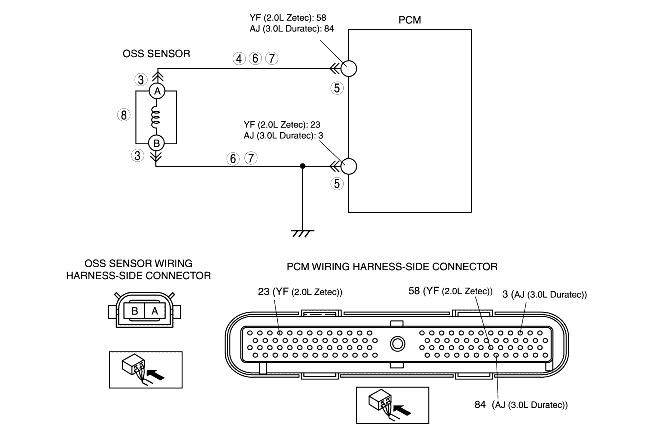
INSPECT OSS SENSOR CONNECTOR FOR POOR CONNECTION
• Turn the ignition switch to the LOCK position.
• Disconnect the OSS sensor connector.
• Inspect for poor connection (such as damaged/pulled-out pins, corrosion)
• Is the connection normal?
|
Yes
|
Go to the next step.
|
|
No
|
Repair or replace connector and/or terminal, then go to Step 9.
|
||
|
4
|
INSPECT OSS SENSOR CIRCUIT FOR SHORT TO GROUND
• Inspect for continuity between OSS sensor connector A (wiring harness-side) and body ground.
• Is there continuity?
|
Yes
|
Repair or replace the wiring harness, then go to Step 9.
|
|
No
|
Go to the next step.
|
||
|
5
|
INSPECT PCM CONNECTOR FOR POOR CONNECTION
• Disconnect the PCM connector.
• Inspect for poor connection (such as damaged/pulled-out pins, corrosion).
• Is the connection normal?
|
Yes
|
Go to the next step.
|
|
No
|
Repair or replace the connector and/or terminals, then go to Step 9.
|
||
|
6
|
INSPECT OSS SENSOR CIRCUIT FOR OPEN CIRCUIT
• Inspect the following OSS sensor terminals (wiring harness-side) and PCM terminals (wiring harness-side):
YF (2.0L Zetec) (2.0L Zetec)
AJ (3.0L Duratec) (3.0L Duratec)
• Is there continuity?
|
Yes
|
Go to the next step.
|
|
No
|
Repair or replace the wiring harness, then go to Step 9.
|
||
|
7
|
INSPECT OSS SENSOR CIRCUIT FOR SHORT TO POWER SUPPLY
• Turn the ignition switch to the ON position (engine off).
• Inspect the voltage at OSS sensor terminals A and B (wiring harness-side).
• Is the voltage 0 V?
|
Yes
|
Go to the next step.
|
|
No
|
Repair or replace the wiring harness, then go to Step 9.
|
||
|
8
|
INSPECT OSS SENSOR
• Inspect the OSS sensor.
• Is OSS sensor normal?
|
Yes
|
Go to the next step.
|
|
No
|
Replace the OSS sensor, then go to the next step.
|
||
|
9
|
VERIFY TROUBLESHOOTING OF DTC P0720 P0721 OR P0722 COMPLETED
• Make sure to reconnect all the disconnected connectors.
• Clear the DTC from memory using the WDS or equivalent.
• Perform the "After Repair Procedure".
• Are any DTCs present?
|
Yes
|
Replace the PCM, then go to the next step.
|
|
No
|
Go to the next step.
|
||
|
10
|
VERIFY DTCS
• Are except DTC P0720, P0721 and P0722 output?
|
Yes
|
Go to the applicable DTC inspection.
(See DTC TABLE [LA4AX-EL (CD4E)].)
|
|
No
|
DTC troubleshooting completed.
|
||