 |
ac5wzw00012876
DTC P3102:00, P3104:00, P3106:00, P3108:00 [PCM (SKYACTIV-D 2.2)]
id0102j5736600
Details On DTCs
|
DESCRIPTION |
Fuel injection amount correction control malfunction between cylinders: • P3102:00: Fuel injection correction amount of cylinder No.1 is too little
• P3104:00: Fuel injection correction amount of cylinder No.2 is too little
• P3106:00: Fuel injection correction amount of cylinder No.3 is too little
• P3108:00: Fuel injection correction amount of cylinder No.4 is too little
|
|
|---|---|---|
|
DETECTION CONDITION
|
Determination conditions
|
• The PCM detects that the FCCB(Fuel Compensation for Cylinders Balancing) correction amount reaches the lower limit during the specified rotation..
|
|
Preconditions
|
• Fuel-cut control is not implemented.
• The following DTCs are not detected:
|
|
|
Malfunction determination period
|
• 58,320 deg CA (Accumulate)
|
|
|
Drive cycle
|
• 2
|
|
|
Self test type
|
• CMDTC self test
|
|
|
Sensor used
|
• Fuel injector No.1
• Fuel injector No.2
• Fuel injector No.3
• Fuel injector No.4
• CKP sensor
• ECT sensor No.1
• CMP sensor
• APP sensor
• Fuel pressure sensor/fuel temperature sensor No.2 (built-into fuel injector No.2)
• Fuel pressure sensor/fuel temperature sensor No.3 (built-into fuel injector No.3)
|
|
|
FAIL-SAFE FUNCTION
|
• Not applicable
|
|
|
VEHICLE STATUS WHEN DTCs ARE OUTPUT
|
• Illuminates check engine light.
|
|
|
POSSIBLE CAUSE
|
• ECT sensor No.1 signal malfunction
• IAT sensor No.1 signal malfunction
• MAF sensor signal malfunction
• CKP sensor signal malfunction
• CMP sensor signal malfunction
• APP sensor signal malfunction
• A/F sensor signal malfunction
• EGR valve position sensor signal malfunction
• EGR cooler bypass valve position sensor signal malfunction
• VSS malfunction
• Fuel injector No.1 malfunction
• Fuel injector No.2 malfunction
• Fuel injector No.3 malfunction
• Fuel injector No.4 malfunction
• Fuel injector No.1 connector or terminals malfunction
• Fuel injector No.2 connector or terminals malfunction
• Fuel injector No.3 connector or terminals malfunction
• Fuel injector No.4 connector or terminals malfunction
• PCM connector or terminals malfunction
• Short to ground in wiring harness between the following terminals:
• Short to power supply in wiring harness between the following terminals:
• Fuel injector No.1 circuits are shorted to each other
• Fuel injector No.2 circuits are shorted to each other
• Fuel injector No.3 circuits are shorted to each other
• Fuel injector No.4 circuits are shorted to each other
• Open circuit in wiring harness between the following terminals:
• Air suction in intake air system
• MAF sensor malfunction
• CMP sensor malfunction
• CKP sensor malfunction
• CKP sensor pulse wheel malfunction
• Fuel system malfunction
• Fuel pressure sensor No.2 (built-into fuel injector No.2) malfunction
• Fuel pressure sensor No.3 (built-into fuel injector No.3) malfunction
• Turbocharger malfunction
• Poor fuel quality
• PCM malfunction
|
|
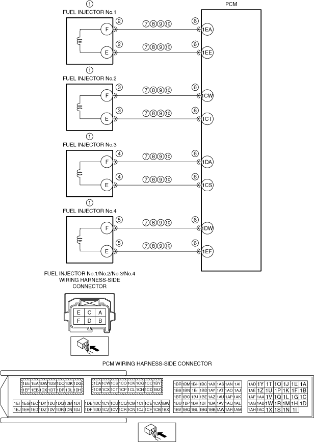
System Wiring Diagram
ac5wzw00012876
|
Function Explanation (DTC Detection Outline)
Repeatability Verification Procedure
PID Item/Simulation Item Used In Diagnosis
PID/DATA monitor item table
|
Item
|
Definition
|
Unit
|
Condition/Specification
|
|
APP
|
Accelerator pedal position
|
%
|
• Accelerator pedal released: Approx. 0%
• Accelerator pedal fully depressed: Approx. 100%
|
|
ECT
|
Engine coolant temperature
|
°C, °F
|
• Displays the ECT.
|
|
EGR_C_BP_ACT
|
Actual measured EGR cooler bypass valve opening angle
|
%
|
ECT: above 70 °C {158 °F}
• Idle: Approx. 0 % (after 20—30 s have elapsed since start the engine)
• Racing (engine speed 2,000 rpm): 0 %
|
|
EGRP_ACT
|
EGR valve actual opening angle
|
%
|
ECT: above 70 °C {158 °F}
• Idle: Approx. 0 % (after 20—30 s have elapsed since start the engine)
• Racing (engine speed 2,000 rpm): Approx. 60 %
|
|
IAT
|
Intake air temperature (No.1)
|
°C, °F
|
• Displays the intake air temperature (No.1).
|
|
MAF
|
Mass air flow
|
g/sec
|
• Switch the ignition ON (engine off): Approx. 1.00 g/s {0.132 lb/min}
• Idle: Approx. 5.47 g/s {0.724 lb/min}
• Racing (engine speed 2,000 rpm): Approx. 13.84 g/s {1.831 lb/min}
• Racing (engine speed 4,000 rpm): Approx. 85.13 g/s {11.26 lb/min}
|
|
O2S11
|
A/F sensor current
|
µA
|
• Idle: Approx. 1.01 mA
• Deceleration fuel cut: Approx. 3.84 mA
|
|
A/F sensor voltage
|
V
|
• Switch ignition ON (engine off): 3.24 V
• Deceleration fuel cut: Approx. 3.74 V
|
|
|
RPM
|
Engine speed
|
RPM
|
• Displays the engine speed.
|
|
VSS
|
Vehicle speed
|
KPH, MPH
|
• Displays the vehicle speed.
|
Function Inspection Using M-MDS
|
STEP |
INSPECTION |
RESULTS |
ACTION |
|---|---|---|---|
|
1
|
PURPOSE: VERIFY RELATED REPAIR INFORMATION AVAILABILITY
• Verify related Service Bulletins and/or on-line repair information availability.
• Is any related repair information available?
|
Yes
|
Perform repair or diagnosis according to the available repair information.
• If the vehicle is not repaired, go to the next step.
|
|
No
|
Go to the next step.
|
||
|
2
|
PURPOSE: IDENTIFY TRIGGER DTC FOR FREEZE FRAME DATA
• Is the DTC P3102:00, P3104:00, P3106:00 or P3108:00 on FREEZE FRAME DATA?
|
Yes
|
Go to the next step.
|
|
No
|
Go to the troubleshooting procedure for DTC on FREEZE FRAME DATA.
|
||
|
3
|
PURPOSE: RECORD VEHICLE STATUS AT TIME OF DTC DETECTION TO UTILIZE WITH REPEATABILITY VERIFICATION
• Record the FREEZE FRAME DATA/snapshot data on the repair order.
|
—
|
Go to the next step.
|
|
4
|
PURPOSE: VERIFY IF THERE IS PID ITEM CAUSING DRASTIC CHANGES OF ACCELERATION FLUCTUATION BY INPUT SIGNAL TO PCM
• Access the following PIDs using the M-MDS:
• Is there any signal that is far out of specification?
|
Yes
|
Go to the next step.
|
|
No
|
Go to the troubleshooting procedure to perform the procedure from Step 1.
|
||
|
5
|
PURPOSE: VERIFY CONNECTOR CONNECTIONS
• Access the following PIDs using the M-MDS:
• When the following parts are shaken, does the PID value include a PID item which has changed?
|
Yes
|
Inspect the related wiring harness and connector.
• Repair or replace the malfunctioning part.
Go to the troubleshooting procedure to perform the procedure from Step 20.
|
|
No
|
Go to the troubleshooting procedure to perform the procedure from Step 1.
|
Troubleshooting Diagnostic Procedure
|
STEP |
INSPECTION |
RESULTS |
ACTION |
|---|---|---|---|
|
1
|
PURPOSE: DETERMINE INTEGRITY OF FUEL INJECTOR No.1—No.4
• Inspect the fuel injector No.1—No.4.
• Is there any malfunction?
|
Yes
|
Replace the suspected fuel injector, then go to Step 20.
|
|
No
|
Go to the next step.
|
||
|
2
|
PURPOSE: INSPECT FUEL INJECTOR No.1 CONNECTOR CONDITION
• Switch the ignition off.
• Disconnect the fuel injector No.1 connector.
• Inspect for poor connection (such as damaged/pulled-out pins, corrosion).
• Is there any malfunction?
|
Yes
|
Repair or replace the connector and/or terminals, then go to Step 20.
|
|
No
|
Go to the next step.
|
||
|
3
|
PURPOSE: INSPECT FUEL INJECTOR No.2 CONNECTOR CONDITION
• Disconnect the fuel injector No.2 connector.
• Inspect for poor connection (such as damaged/pulled-out pins, corrosion).
• Is there any malfunction?
|
Yes
|
Repair or replace the connector and/or terminals, then go to Step 20.
|
|
No
|
Go to the next step.
|
||
|
4
|
PURPOSE: INSPECT FUEL INJECTOR No.3 CONNECTOR CONDITION
• Disconnect the fuel injector No.3 connector.
• Inspect for poor connection (such as damaged/pulled-out pins, corrosion).
• Is there any malfunction?
|
Yes
|
Repair or replace the connector and/or terminals, then go to Step 20.
|
|
No
|
Go to the next step.
|
||
|
5
|
PURPOSE: INSPECT FUEL INJECTOR No.4 CONNECTOR CONDITION
• Disconnect the fuel injector No.4 connector.
• Inspect for poor connection (such as damaged/pulled-out pins, corrosion).
• Is there any malfunction?
|
Yes
|
Repair or replace the connector and/or terminals, then go to Step 20.
|
|
No
|
Go to the next step.
|
||
|
6
|
PURPOSE: INSPECT PCM CONNECTOR CONDITION
• Disconnect the PCM connector.
• Inspect for poor connection (such as damaged/pulled-out pins, corrosion).
• Is there any malfunction?
|
Yes
|
Repair or replace the connector and/or terminals, then go to Step 20.
|
|
No
|
Go to the next step.
|
||
|
7
|
PURPOSE: INSPECT FUEL INJECTOR CIRCUIT FOR SHORT TO GROUND
• Verify that the fuel injector No.1, No.2, No.3, No.4 and PCM connectors are disconnected.
• Inspect for continuity between the following terminals (wiring harness-side) and body ground:
• Is there continuity?
|
Yes
|
Refer to the wiring diagram and verify whether or not there is a common connector between the following terminals:
• Fuel injector No.1 terminal F—PCM terminal 1EA
• Fuel injector No.1 terminal E—PCM terminal 1EE
• Fuel injector No.2 terminal F—PCM terminal 1CW
• Fuel injector No.2 terminal E—PCM terminal 1CT
• Fuel injector No.3 terminal F—PCM terminal 1DA
• Fuel injector No.3 terminal E—PCM terminal 1CS
• Fuel injector No.4 terminal F—PCM terminal 1DW
• Fuel injector No.4 terminal E—PCM terminal 1EF
If there is a common connector:
• Determine the malfunctioning part by inspecting the common connector and the terminal for corrosion, damage, or pin disconnection, and the common wiring harness for a short to ground.
• Repair or replace the malfunctioning part.
If there is no common connector:
• Repair or replace the wiring harness which has a short to ground.
Go to Step 20.
|
|
No
|
Go to the next step.
|
||
|
8
|
PURPOSE: INSPECT FUEL INJECTOR CIRCUIT FOR SHORT TO POWER SUPPLY
• Verify that the fuel injector No.1, No.2, No.3, No.4 and PCM connectors are disconnected.
• Switch the ignition ON (engine off).
• Measure the voltage at the following terminals (wiring harness-side):
• Is the voltage 0 V?
|
Yes
|
Go to the next step.
|
|
No
|
Refer to the wiring diagram and verify whether or not there is a common connector between the following terminals:
• Fuel injector No.1 terminal F—PCM terminal 1EA
• Fuel injector No.1 terminal E—PCM terminal 1EE
• Fuel injector No.2 terminal F—PCM terminal 1CW
• Fuel injector No.2 terminal E—PCM terminal 1CT
• Fuel injector No.3 terminal F—PCM terminal 1DA
• Fuel injector No.3 terminal E—PCM terminal 1CS
• Fuel injector No.4 terminal F—PCM terminal 1DW
• Fuel injector No.4 terminal E—PCM terminal 1EF
If there is a common connector:
• Determine the malfunctioning part by inspecting the common connector and the terminal for corrosion, damage, or pin disconnection, and the common wiring harness for a short to power supply.
• Repair or replace the malfunctioning part.
If there is no common connector:
• Repair or replace the wiring harness which has a short to power supply.
Go to Step 20.
|
||
|
9
|
PURPOSE: INSPECT FUEL INJECTOR CIRCUITS FOR SHORT TO EACH OTHER
• Verify that the fuel injector No.1, No.2, No.3, No.4 and PCM connectors are disconnected.
• Switch the ignition off.
• Inspect for continuity between the following terminals (wiring harness-side):
• Is there continuity?
|
Yes
|
Refer to the wiring diagram and verify whether or not there is a common connector between the following terminals:
• Fuel injector No.1 terminal F—PCM terminal 1EA
• Fuel injector No.1 terminal E—PCM terminal 1EE
• Fuel injector No.2 terminal F—PCM terminal 1CW
• Fuel injector No.2 terminal E—PCM terminal 1CT
• Fuel injector No.3 terminal F—PCM terminal 1DA
• Fuel injector No.3 terminal E—PCM terminal 1CS
• Fuel injector No.4 terminal F—PCM terminal 1DW
• Fuel injector No.4 terminal E—PCM terminal 1EF
If there is a common connector:
• Determine the malfunctioning part by inspecting the common connector and the terminal for corrosion, damage, or pin disconnection, and the common wiring harness for a short to each other.
• Repair or replace the malfunctioning part.
If there is no common connector:
• Repair or replace the wiring harness which has a short to each other.
Go to Step 20.
|
|
No
|
Go to the next step.
|
||
|
10
|
PURPOSE: INSPECT FUEL INJECTOR CIRCUIT FOR OPEN CIRCUIT
• Verify that the fuel injector No.1, No.2, No.3, No.4 and PCM connectors are disconnected.
• Inspect for continuity between the following terminals (wiring harness-side):
• Is there continuity?
|
Yes
|
Go to the next step.
|
|
No
|
Refer to the wiring diagram and verify whether or not there is a common connector between the following terminals:
• Fuel injector No.1 terminal F—PCM terminal 1EA
• Fuel injector No.1 terminal E—PCM terminal 1EE
• Fuel injector No.2 terminal F—PCM terminal 1CW
• Fuel injector No.2 terminal E—PCM terminal 1CT
• Fuel injector No.3 terminal F—PCM terminal 1DA
• Fuel injector No.3 terminal E—PCM terminal 1CS
• Fuel injector No.4 terminal F—PCM terminal 1DW
• Fuel injector No.4 terminal E—PCM terminal 1EF
If there is a common connector:
• Determine the malfunctioning part by inspecting the common connector and the terminal for corrosion, damage, or pin disconnection, and the common wiring harness for an open circuit.
• Repair or replace the malfunctioning part.
If there is no common connector:
• Repair or replace the wiring harness which has an open circuit.
Go to Step 20.
|
||
|
11
|
PURPOSE: VERIFY IF MALFUNCTION RELATED TO INTAKE AIR SYSTEM AFFECTS DIAGNOSTIC RESULTS
• Visually inspect for loose, cracked or damaged hoses on intake air system.
• Is there any malfunction?
|
Yes
|
Repair or replace the malfunctioning part according to the inspection results, then go to Step 20.
|
|
No
|
Go to the next step.
|
||
|
12
|
PURPOSE: INSPECT MAF SENSOR
• Reconnect all disconnected connectors.
• Inspect the MAF sensor.
• Is there any malfunction?
|
Yes
|
Replace the MAF sensor/IAT sensor No.1, then go to Step 20.
|
|
No
|
Go to the next step.
|
||
|
13
|
PURPOSE: INSPECT CMP SENSOR
• Inspect the CMP sensor.
• Is there any malfunction?
|
Yes
|
Replace the CMP sensor, then go to Step 20.
|
|
No
|
Go to the next step.
|
||
|
14
|
PURPOSE: INSPECT CKP SENSOR
• Inspect the CKP sensor.
• Is there any malfunction?
|
Yes
|
Replace the CKP sensor, then go to Step 20.
|
|
No
|
Go to the next step.
|
||
|
15
|
PURPOSE: INSPECT CKP SENSOR PULSE WHEEL
• Visually inspect the CKP sensor pulse wheel.
• Are there any damage or scratches at the CKP sensor pulse wheel?
|
Yes
|
Replace the CKP sensor pulse wheel, then go to Step 20.
|
|
No
|
Go to the next step.
|
||
|
16
|
PURPOSE: INSPECT FOR FUEL LEAKAGE FROM FUEL SYSTEM
• Visually inspect the following:
• Are all items normal?
|
Yes
|
Go to the next step.
|
|
No
|
Repair or replace the malfunctioning part according to the inspection results, then go to Step 20.
|
||
|
17
|
PURPOSE: INSPECT FUEL INJECTION RELATED PARTS
• Inspect the following parts:
• Are all items normal?
|
Yes
|
Go to the next step.
|
|
No
|
Repair or replace the malfunctioning part according to the inspection results, then go to Step 20.
|
||
|
18
|
PURPOSE: INSPECT FUEL PRESSURE SENSOR
• Inspect the fuel pressure sensor No.2 and fuel pressure sensor No.3.
• Is there any malfunction?
|
Yes
|
Replace the fuel pressure sensor No.2 and/or fuel pressure sensor No.3, then go to Step 20.
|
|
No
|
Go to the next step.
|
||
|
19
|
PURPOSE: INSPECT TURBOCHARGER
• Inspect the turbocharger.
• Is there any malfunction?
|
Yes
|
Replace the turbocharger, then go to the next step.
|
|
No
|
Go to the next step.
|
||
|
20
|
PURPOSE: VERIFICATION OF VEHICLE REPAIR COMPLETION
• Always reconnect all disconnected connectors.
• Clear the DTC from the PCM memory using the M-MDS.
• Implement the repeatability verification procedure.
• Perform the Pending Trouble Code Access Procedure.
• Is the PENDING CODE for this DTC present?
|
Yes
|
Repeat the inspection from Step 1.
• If the malfunction recurs, replace the PCM.
Go to the next step.
|
|
No
|
Go to the next step.
|
||
|
21
|
PURPOSE: VERIFY IF THERE IS ANY OTHER MALFUNCTION
• Is any other DTC or pending code stored?
|
Yes
|
Go to the applicable DTC inspection.
|
|
No
|
DTC troubleshooting completed.
|