|
1
|
VERIFY PCM DTCs
• Retrieve the PCM DTCs using the M-MDS.
• Are any DTCs displayed?
|
Yes
|
Repair or replace the malfunctioning part according to the applicable DTC troubleshooting.
|
|
No
|
Go to the next step.
|
|
2
|
VERIFY DC-DC CONVERTER (i-ELOOP) DTCs
• Retrieve the DC-DC converter (i-ELOOP) DTCs using the M-MDS.
• Are any DTCs displayed?
|
Yes
|
Repair or replace the malfunctioning part according to the applicable DTC troubleshooting.
|
|
No
|
Go to the next step.
|
|
3
|
INSPECT BATTERY
• Is the battery normal?
|
Yes
|
Go to the next step.
|
|
No
|
Recharge or replace the battery, then go to Step 8.
|
|
4
|
INSPECT GENERATOR
• Is the generator normal?
|
Yes
|
Go to the next step.
|
|
No
|
Replace the generator, then go to Step 8.
|
|
5
|
INSPECT IGNITION RELAY (IG1_STAB)
• Switch the ignition off.
• Disconnect the negative battery terminal.
• Remove the ignition relay (IG1_STAB).
• Inspect the ignition relay (IG1_STAB).
• Is the ignition relay (IG1_STAB) normal?
|
Yes
|
Go to the next step.
|
|
No
|
Replace the ignition relay (IG1_STAB), then go to Step 8.
|
|
6
|
INSPECT ACTIVE DRIVING DISPLAY CONNECTOR CONDITION
• Disconnect the active driving display connector.
• Inspect the connector engagement and connection condition and inspect the terminals for damage, deformation, corrosion, or disconnection.
• Is the connector normal?
|
Yes
|
Go to the next step.
|
|
No
|
Repair or replace the connector, then go to Step 8.
|
|
7
|
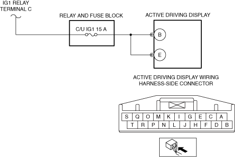
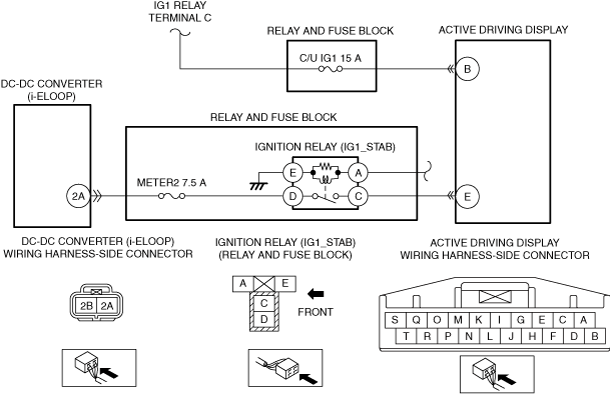
VERIFY ACTIVE DRIVING DISPLAY POWER SUPPLY VOLTAGE
• Always reconnect all disconnected connectors.
• Connect the negative battery terminal.
• Switch the ignition ON (engine off or on).
• Measure the voltage at the following terminal (wiring harness-side).
-
― Active driving display terminal B
― Active driving display terminal E
• Is the voltage B+?
|
Yes
|
Go to the next step.
|
|
No
|
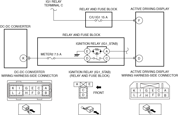
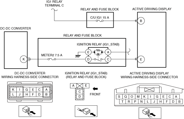
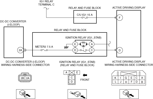
Inspect the C/U IG1 15 A fuse and METER2 7.5 A fuse.
• If the fuse is blown:
-
― Refer to the wiring diagram and verify whether or not there is a common connector between the following terminal.
-
• C/U IG1 15 A fuse and active driving display terminal B
• METER2 7.5 A fuse and active driving display terminal E
If there is a common connector:
-
• Determine the malfunctioning part by inspecting the common connector and the terminal for corrosion, damage, or pin disconnection, and the common wiring harness for a short to ground.
• Repair or replace the malfunctioning part.
If there is no common connector:
-
• Repair or replace the wiring harness which has a short to ground.
• Replace the fuse.
• If the fuse is damaged:
-
― Replace the fuse.
• If the fuse is normal:
-
― Refer to the wiring diagram and verify whether or not there is a common connector between the following terminal.
-
• IG1 relay terminal C and active driving display terminal B
• ignition relay (IG1_STAB) terminal C and active driving display terminal E
If there is a common connector:
-
• Determine the malfunctioning part by inspecting the common connector and the terminal for corrosion, damage, or pin disconnection, and the common wiring harness for a short to ground.
• Repair or replace the malfunctioning part.
If there is no common connector:
-
• Repair or replace the wiring harness which has a short to ground.
Go to the next step.
|
|
8
|
VERIFY THAT REPAIRS HAVE BEEN COMPLETED
• Always reconnect all disconnected connectors.
• Connect the negative battery terminal.
• Clear the DTC for the active driving display using the M-MDS.
• Retrieve the active driving display DTCs using the M-MDS.
• Is the same DTC displayed?
|
Yes
|
Repeat the inspection from Step 1.
• If the malfunction recurs, replace the active driving display.
Go to the next step.
|
|
No
|
Go to the next step.
|
|
9
|
VERIFY IF OTHER DTCs DISPLAYED
• Are any other DTCs displayed?
|
Yes
|
Repair or replace the malfunctioning part according to the applicable DTC troubleshooting.
|
|
No
|
DTC troubleshooting completed.
|