 |
ac5uuw00004015
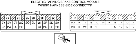
ELECTRIC PARKING BRAKE CONTROL MODULE INSPECTION
id041200523500
1. Remove the following parts.
2. Measure the terminal voltage of the electric parking brake control module using a tester.
Terminal Voltage Table (Reference)
ac5uuw00004015
|
|
Terminal |
Connected to |
Test condition |
Specification |
Inspection item(s) |
|---|---|---|---|---|
|
1A
|
—
|
—
|
—
|
—
|
|
1B
|
—
|
—
|
—
|
—
|
|
1C
|
Battery
|
Under any condition
|
B+
|
• Wiring harness between electric parking brake control module terminal 1C and battery
|
|
1D
|
—
|
—
|
—
|
—
|
|
1E
|
—
|
—
|
—
|
—
|
|
1F
|
—
|
—
|
—
|
—
|
|
1G
|
—
|
—
|
—
|
—
|
|
1H
|
Battery
|
Under any condition
|
B+
|
• Wiring harness between electric parking brake control module terminal 1H and battery
|
|
1I
|
—
|
—
|
—
|
—
|
|
1J
|
—
|
—
|
—
|
—
|
|
1K
|
—
|
—
|
—
|
—
|
|
1M
|
Electric parking brake motor gear unit (RH)
|
Electric parking brake switch is in neutral position
|
6.0—7.0 V
|
• Wiring harness between electric parking brake control module terminal 1M and electric parking brake motor gear unit (RH) terminal B
|
|
Electric parking brake is releasing while electric parking brake switch is pushed down
|
B+
|
|||
|
Electric parking brake is applying while electric parking brake switch is pulled up
|
1.0 V or less
|
|||
|
1N
|
—
|
—
|
—
|
—
|
|
1P
|
Electric parking brake motor gear unit (RH)
|
Electric parking brake switch is in neutral position
|
6.0—7.0 V
|
• Wiring harness between electric parking brake control module terminal 1P and electric parking brake motor gear unit (RH) terminal A
|
|
Electric parking brake is releasing while electric parking brake switch is pushed down
|
1.0 V or less
|
|||
|
Electric parking brake is applying while electric parking brake switch is pulled up
|
B+
|
|||
|
1Q
|
—
|
—
|
—
|
—
|
|
1R
|
Indicator light built into electric parking brake switch
|
Indicator light off
|
1.0 V or less
|
• Wiring harness between electric parking brake control module terminal 1R and electric parking brake switch terminal L
|
|
Indicator light on
|
B+
|
|||
|
1S
|
—
|
—
|
—
|
—
|
|
1T
|
—
|
—
|
—
|
—
|
|
1U
|
Electric parking brake motor gear unit (LH)
|
Electric parking brake switch is in neutral position
|
6.0—7.0 V
|
• Wiring harness between electric parking brake control module terminal 1U and electric parking brake motor gear unit (LH) terminal A
|
|
Electric parking brake is releasing while electric parking brake switch is pushed down
|
1.0 V or less
|
|||
|
Electric parking brake is applying while electric parking brake switch is pulled up
|
B+
|
|||
|
1V
|
—
|
—
|
—
|
—
|
|
1W
|
Electric parking brake switch
|
Electric parking brake switch is in neutral position
|
4.3 V
|
• Wiring harness between electric parking brake control module terminal 1W and electric parking brake switch terminal H
|
|
Electric parking brake switch is pushed down
|
4.3 V
|
|||
|
Electric parking brake switch is pulled up
|
4.3 V
|
|||
|
1X
|
—
|
—
|
—
|
—
|
|
1Y
|
—
|
—
|
—
|
—
|
|
1Z
|
Electric parking brake motor gear unit (LH)
|
Electric parking brake switch is in neutral position
|
6.0—7.0 V
|
• Wiring harness between electric parking brake control module terminal 1Z and electric parking brake motor gear unit (LH) terminal B
|
|
Electric parking brake is releasing while electric parking brake switch is pushed down
|
B+
|
|||
|
Electric parking brake is applying while electric parking brake switch is pulled up
|
1.0 V or less
|
|||
|
1AA
|
—
|
—
|
—
|
—
|
|
1AB
|
IG1 relay
|
Ignition off
|
1.0 V or less
|
• Wiring harness electric parking brake control module terminal 1AB and IG1 relay
|
|
Ignition ON
|
B+
|
|||
|
2A
|
—
|
—
|
—
|
—
|
|
2B
|
—
|
—
|
—
|
—
|
|
2C
|
Ground point
|
Under any condition
|
1.0 V or less
|
• Wiring harness between electric parking brake control module terminal 2C and ground point
|
|
2D
|
AUTO HOLD switch
|
AUTO HOLD switch is in neutral position
|
4.50 V
|
• Wiring harness between electric parking brake control module terminal 2D and electric parking brake switch terminal D
|
|
AUTO HOLD switch is pushed down
|
1.0 V or less
|
|||
|
2E
|
—
|
—
|
—
|
—
|
|
2F
|
CAN related module
|
Because this terminal is for communication, determination using terminal voltage inspection is not possible. Perform the inspection using the DTC inspection.
|
||
|
2G
|
CAN related module
|
Because this terminal is for communication, determination using terminal voltage inspection is not possible. Perform the inspection using the DTC inspection.
|
||
|
2H
|
Ground point
|
Under any condition
|
1.0 V or less
|
• Wiring harness between electric parking brake control module terminal 2H and ground point
|
|
2I
|
—
|
—
|
—
|
—
|
|
2J
|
—
|
—
|
—
|
—
|
|
2K
|
Electric parking brake switch
|
Electric parking brake switch is in neutral position
|
2.4 V
|
• Wiring harness between electric parking brake control module terminal 2K and electric parking brake switch terminal C
|
|
Electric parking brake switch is pushed down
|
2.4 V
|
|||
|
Electric parking brake switch is pulled up
|
2.3 V
|
|||
|
2L
|
Electric parking brake switch
|
Electric parking brake switch is in neutral position
|
3.1 V
|
• Wiring harness between electric parking brake control module terminal 2L and electric parking brake switch terminal G
|
|
Electric parking brake switch is pushed down
|
1.2 V
|
|||
|
Electric parking brake switch is pulled up
|
1.9 V
|
|||
|
2N
|
—
|
—
|
—
|
—
|
|
2O
|
—
|
—
|
—
|
—
|
|
2Q
|
Electric parking brake switch
|
Electric parking brake switch is in neutral position
|
1.2 V
|
• Wiring harness between electric parking brake control module terminal 2Q and electric parking brake switch terminal E
|
|
Electric parking brake switch is pushed down
|
3.1 V
|
|||
|
Electric parking brake switch is pulled up
|
3.7 V
|
|||
|
2R
|
—
|
—
|
—
|
—
|
|
2S
|
—
|
—
|
—
|
—
|
|
2T
|
—
|
—
|
—
|
—
|
|
2U
|
—
|
—
|
—
|
—
|
|
2V
|
—
|
—
|
—
|
—
|
|
2W
|
—
|
—
|
—
|
—
|
|
2X
|
Indicator light built into AUTO HOLD switch
|
Indicator light off
|
B+
|
• Wiring harness between electric parking brake control module terminal 2X and electric parking brake switch terminal B
|
|
Indicator light on
|
1.0 V or less
|
|||
|
2Y
|
—
|
—
|
—
|
—
|
|
2Z
|
—
|
—
|
—
|
—
|