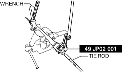
49 JP02 001
Adjustable wrench

49 B032 317
Bearing & oil seal remover

49 T028 301
Dust boot installer

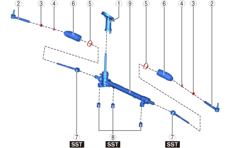
STEERING GEAR AND LINKAGE DISASSEMBLY
id061300801800
Special service tool (SST)
|
49 JP02 001
Adjustable wrench
|
|
49 B032 317
Bearing & oil seal remover
|
|
49 T028 301
Dust boot installer
|
|
1. Remove the wheel and tire. (See WHEEL AND TIRE REMOVAL/INSTALLATION.)
2. Disconnect the front ABS wheel-speed sensor wiring harness on the steering knuckle and set it aside so that it does not interfere with the servicing.
ac8wzw00001508
|
3. Remove the following parts.
4. Disconnect the tie-rod end from the steering knuckle. (See TIE-ROD END REPLACEMENT.)
5. Disconnect the front lower arm ball joint from the steering knuckle. (See FRONT LOWER ARM REMOVAL/INSTALLATION.)
6. Remove the joint cover. (See INTERMEDIATE SHAFT REMOVAL/INSTALLATION.)
7. Disconnect the intermediate shaft from the steering gear and linkage. (See INTERMEDIATE SHAFT REMOVAL/INSTALLATION.)
8. Remove the front crossmember component. (See FRONT CROSSMEMBER REMOVAL/INSTALLATION.)
9. Remove the steering gear and linkage from the front crossmember component. (See STEERING GEAR AND LINKAGE REMOVAL/INSTALLATION.)
10. Disassemble in the order shown in the figure.
ac8jjw00001359
|
|
1
|
Dust cover
|
|
2
|
Tie-rod end
(See Tie-rod End Disassembly Note.)
|
|
3
|
Locknut
|
|
4
|
Boot clamp
|
|
5
|
Boot band
(See Boot Band Disassembly Note.)
|
|
6
|
Boot
|
|
7
|
Tie rod
(See Tie Rod Disassembly Note.)
|
|
8
|
Mounting rubber
|
|
9
|
Steering gear
|
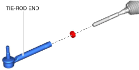
Tie-rod End Disassembly Note
1. Place alignment marks as shown in the figure for reference in assembly.
ac8wzw00001509
|
2. Remove the tie-rod end.
ac8wzw00001510
|
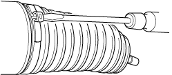
Boot Band Disassembly Note
1. Insert a flathead screwdriver into the crimped part of the boot clamp, expand the crimped part, and then remove the boot clamp as shown in the figure.
ac5wzw00001035
|
Tie Rod Disassembly Note
1. Lock the steering gear against rotation using a wrench and remove the tie rod using the SST.
ac8wzw00001511
|
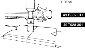
Mounting Rubber Disassembly Note
1. Remove the mounting rubber from the gear housing using the SST and a press.
ac8wzw00001512
|