 |
ac5wzw00010257
FUEL GAUGE SENDER UNIT INSPECTION [4WD]
id0922000121b3
SKYACTIV-G 2.5
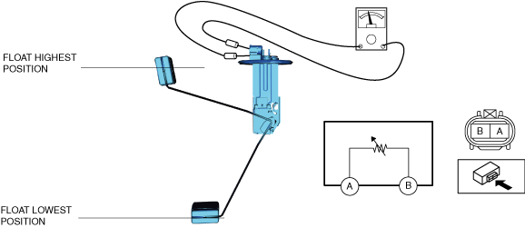
Fuel gauge sender unit (main)
1. Verify that the resistance at fuel gauge sender unit (main) terminals A and C is as follows according to the height of the float.
ac5wzw00010257
|
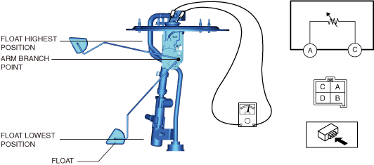
Fuel gauge sender unit (sub)
1. Perform the "Fuel Line Safety Procedure" referring to the "BEFORE SERVICE PRECAUTION". (See BEFORE SERVICE PRECAUTION [SKYACTIV-G 2.5].)
2. If the fuel gauge level indicates 3/4 or more, refer to the "FUEL DRAINING PROCEDURE" and drain the fuel. (See FUEL DRAINING PROCEDURE [SKYACTIV-G 2.5].)
3. Disconnect the negative battery terminal. (See NEGATIVE BATTERY TERMINAL DISCONNECTION/CONNECTION.)
4. Remove the second-row seat. (See SECOND-ROW SEAT REMOVAL/INSTALLATION.)
5. Remove the fuel gauge sender unit (sub). (See FUEL GAUGE SENDER UNIT REMOVAL/INSTALLATION [4WD].)
6. Verify that the resistance at fuel gauge sender unit (sub) terminals A and B is as follows according to the height of the float.
ac5wzw00010258
|
SKYACTIV-D 2.2
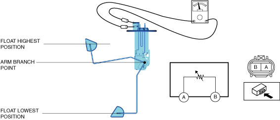
Fuel gauge sender unit (main)
1. Perform the "Fuel Line Safety Procedure" referring to the "BEFORE SERVICE PRECAUTION". (See BEFORE SERVICE PRECAUTION [SKYACTIV-D 2.2].)
2. If the fuel gauge level indicates 3/4 or more, refer to the "FUEL DRAINING PROCEDURE" and drain the fuel. (See FUEL DRAINING PROCEDURE [SKYACTIV-D 2.2].)
3. Disconnect the negative battery terminal. (See NEGATIVE BATTERY TERMINAL DISCONNECTION/CONNECTION.)
4. Remove the second-row seat. (See SECOND-ROW SEAT REMOVAL/INSTALLATION.)
5. Remove the fuel gauge sender unit (main). (See FUEL GAUGE SENDER UNIT REMOVAL/INSTALLATION [4WD].)
6. Verify that the resistance at fuel gauge sender unit (main) terminals A and C is as follows according to the height of the float.
ac8wzw00003128
|
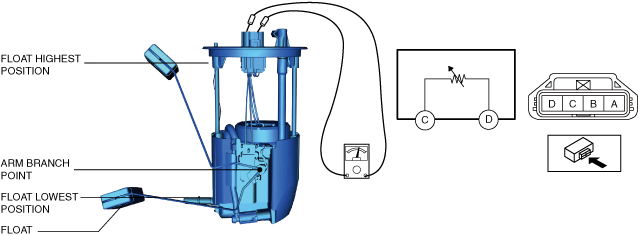
Fuel gauge sender unit (sub)
1. Perform the "Fuel Line Safety Procedure" referring to the "BEFORE SERVICE PRECAUTION". (See BEFORE SERVICE PRECAUTION [SKYACTIV-D 2.2].)
2. If the fuel gauge level indicates 3/4 or more, refer to the "FUEL DRAINING PROCEDURE" and drain the fuel. (See FUEL DRAINING PROCEDURE [SKYACTIV-D 2.2].)
3. Disconnect the negative battery terminal. (See NEGATIVE BATTERY TERMINAL DISCONNECTION/CONNECTION.)
4. Remove the second-row seat. (See SECOND-ROW SEAT REMOVAL/INSTALLATION.)
5. Remove the rear scuff plate. (See REAR SCUFF PLATE REMOVAL/INSTALLATION.)
6. Remove the fuel gauge sender unit (sub). (See FUEL GAUGE SENDER UNIT REMOVAL/INSTALLATION [4WD].)
7. Verify that the resistance at fuel gauge sender unit (sub) terminals A and B is as follows according to the height of the float.
ac8wzw00001424
|