 |
ac9uuw00004132
FRONT PLANETARY GEAR COMPONENT AND INPUT SHAFT REMOVAL/INSTALLATION [AY6A-EL, AY6AX-EL]
id0517k3332900
1. Drain the ATF. (See AUTOMATIC TRANSAXLE FLUID (ATF) REPLACEMENT [AY6A-EL, AY6AX-EL].)
2. Remove the transaxle. (See AUTOMATIC TRANSAXLE REMOVAL/INSTALLATION [AY6A-EL, AY6AX-EL].)
3. Clean the transaxle. (See AUTOMATIC TRANSAXLE CLEANING [AY6A-EL, AY6AX-EL].)
4. Remove the torque converter. (See TORQUE CONVERTER REMOVAL/INSTALLATION [AY6A-EL, AY6AX-EL].)
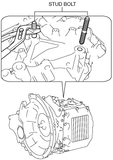
5. Remove the stud bolts.
ac9uuw00004132
|
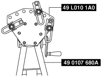
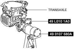
6. Set the SSTs as shown in the figure.
ac9wzw00002030
|
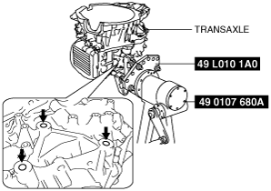
7. Install the transaxle to the SSTs.
ac9wzw00002032
|
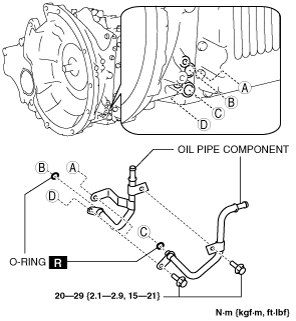
8. Remove the oil pipe component and the O-rings.
ac9uuw00004133
|
9. Refer to the “AUTOMATIC TRANSAXLE DISASSEMBLY/ASSEMBLY PRECAUTION” before disassembling/assembling the transaxle. (See AUTOMATIC TRANSAXLE DISASSEMBLY/ASSEMBLY PRECAUTION [AY6A-EL, AY6AX-EL].)
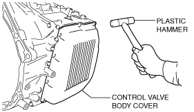
10. Remove the control valve body cover.
am6xuw00004095
|
11. Using a plastic hammer, tap the control valve body cover to remove it.
ac9uuw00003980
|
ac9uuw00004054
|
ac9uuw00004055
|
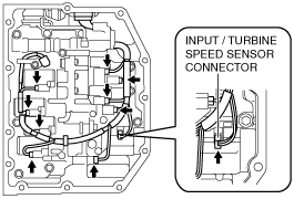
12. Disconnect the solenoid connectors, VSS connector and the input/turbine speed sensor connector.
ac9uuw00003983
|
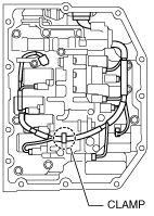
13. Disconnect the coupler component from the clamp.
ac9uuw00004134
|
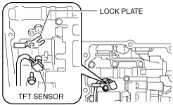
14. Remove the lock plate, and pull out the TFT sensor from the control valve body.
ac9uuw00004056
|
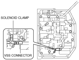
15. Remove the VSS connector from the solenoid clamp.
ac9uuw00003985
|
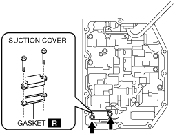
16. Remove the suction cover and the gasket.
ac9uuw00004058
|
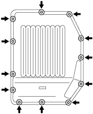
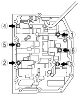
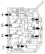
17. Remove the control valve body installation bolts in the order shown in the figure.
ac9uuw00004059
|
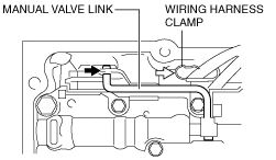
18. Disconnect the manual valve link and remove the control valve body component.
ac9uuw00004060
|
19. Fix the coupler component with tape to the transaxle case as shown in the figure.
ac9uuw00004392
|
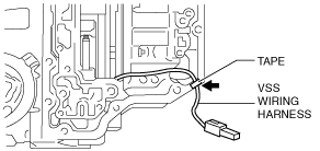
20. Fix the VSS wiring harness with tape to the transaxle case as shown in the figure.
ac9uuw00004393
|
21. Remove the converter housing. (See CONVERTER HOUSING REMOVAL/INSTALLATION [AY6A-EL, AY6AX-EL].)
22. Remove the oil pump component and oil strainer as a single unit. (See OIL PUMP REMOVAL/INSTALLATION [AY6A-EL, AY6AX-EL].)
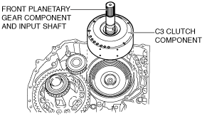
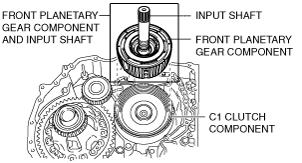
23. Remove the C3 clutch component, front planetary gear component and input shaft.
am6xuw00004200
|
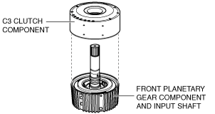
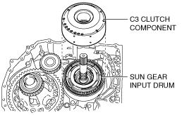
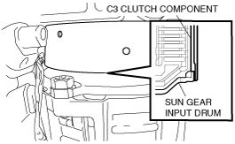
24. Remove the C3 clutch component from the front planetary gear component and input shaft.
am6xuw00004064
|
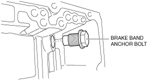
25. Remove the brake band anchor bolt.
am6xuw00004189
|
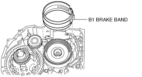
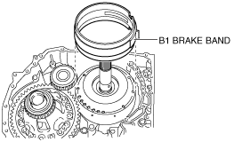
26. Remove the B1 brake band.
am6xuw00004190
|
27. Install the front planetary gear component and input shaft to the transaxle case.
ac9uuw00004135
|
28. Apply ATF to the bushing of the C3 clutch component.
29. Install the C3 clutch component to the transaxle case.
ac9uuw00004136
|
ac9uuw00004137
|
30. Install the B1 brake band to the transaxle case.
am6xuw00004194
|
31. Install the brake band anchor bolt to the transaxle case.
am6xuw00004189
|
32. Install the oil pump component and oil strainer as a single unit. (See OIL PUMP REMOVAL/INSTALLATION [AY6A-EL, AY6AX-EL].)
33. Install the converter housing. (See CONVERTER HOUSING REMOVAL/INSTALLATION [AY6A-EL, AY6AX-EL].)
34. Connect the manual valve link and install the control valve body component.
ac9uuw00004213
|
35. Temporarily install the control valve body component with the bolts.
ac9uuw00004064
|
36. Temporarily install the suction cover and a new gasket with the bolts.
ac9uuw00004058
|
37. Tighten the bolts in the order shown in the figure.
ac9uuw00004065
|
38. Install the connector of the VSS to the solenoid clamp.
ac9uuw00003985
|
39. Install the TFT sensor with the lock plate and a bolt to the control valve body component as shown in the figure.
ac9uuw00004056
|
40. Connect the solenoid connectors, VSS connector and the input/turbine speed sensor connector.
ac9uuw00003983
|
41. Connect the coupler component to the clamps.
ac9uuw00004134
|
42. Clean sealant and oil off the contact surface of the transaxle case with the control valve body cover and the bolt holes.
ac9uuw00004066
|
43. Clean oil off the contact surface of the new control valve body cover with the transaxle case.
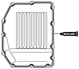
44. Apply sealant to the new control valve body cover as shown in the figure.
am6xuw00004155
|
45. Install the new control valve body cover with new seal bolts before the applied sealant starts to harden.
am6xuw00004095
|
46. Install the oil pipe component and new O-rings.
ac9uuw00004133
|
47. Remove the transaxle from the SSTs.
ac9wzw00002031
|
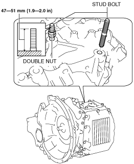
48. Install the stud bolts using double nutted.
ac9uuw00003997
|
49. Remove the double nutted from the stud bolts.
50. Install the torque converter. (See TORQUE CONVERTER REMOVAL/INSTALLATION [AY6A-EL, AY6AX-EL].)
51. Install the transaxle. (See AUTOMATIC TRANSAXLE REMOVAL/INSTALLATION [AY6A-EL, AY6AX-EL].)
52. Add ATF. (See AUTOMATIC TRANSAXLE FLUID (ATF) LEVEL ADJUSTMENT [AY6A-EL, AY6AX-EL].)
53. Adjust the ATF level. (See AUTOMATIC TRANSAXLE FLUID (ATF) LEVEL ADJUSTMENT [AY6A-EL, AY6AX-EL].)
54. Perform the “MECHANICAL SYSTEM TEST”. (See MECHANICAL SYSTEM TEST [AY6A-EL, AY6AX-EL].)
55. Perform the “ROAD TEST”. (See ROAD TEST [AY6A-EL, AY6AX-EL].)