|
ac9wzw00000615
FRONT OIL SEAL REPLACEMENT [MZI-3.7]
id0110c5800800
1. Disconnect the negative battery cable.
2. Remove the engine cover. (See ENGINE COVER REMOVAL/INSTALLATION [MZI-3.7].)
3. Position the power steering reserve tank out of the way. (See POWER STEERING OIL PUMP REMOVAL/INSTALLATION [L.H.D.].) (See POWER STEERING OIL PUMP REMOVAL/INSTALLATION [R.H.D.].)
4. Remove the both front wheels and tires. (See GENERAL PROCEDURES (SUSPENSION).)
5. Remove the splash shield (RH).
6. Position the both ABS wheel-speed sensor out of the way. (See FRONT ABS WHEEL-SPEED SENSOR REMOVAL/INSTALLATION.)
7. Position the front stabilizer control link (lower side) (RH) out of the way. (See FRONT STABILIZER REMOVAL/INSTALLATION [L.H.D.].) (See FRONT STABILIZER REMOVAL/INSTALLATION [R.H.D.].)
8. Position the tie-rod end ball joint (RH) out of the way. (See FRONT CROSSMEMBER REMOVAL/INSTALLATION [L.H.D.].) (See FRONT CROSSMEMBER REMOVAL/INSTALLATION [R.H.D.].)
9. Remove the front shock absorber (LH) lower side bolts, position and secure the wheel hub and steering knuckle component (LH) out of the way with a rope or wire. (See FRONT SHOCK ABSORBER AND COIL SPRING REMOVAL/INSTALLATION.)
10. Disconnect the front drive shaft (RH) from the joint shaft side. (See FRONT DRIVE SHAFT REMOVAL/INSTALLATION.)
11. Remove the front pipe and middle pipe as a single unit. (See EXHAUST SYSTEM REMOVAL/INSTALLATION [MZI-3.7].)
12. Position the propeller shaft out of the way. (See PROPELLER SHAFT REMOVAL/INSTALLATION.)
13. Remove the generator and A/C drive belt. (See DRIVE BELT REMOVAL/INSTALLATION [MZI-3.7].)
14. Remove the power steering oil pump drive belt. (See DRIVE BELT REMOVAL/INSTALLATION [MZI-3.7].)
15. Remove in the order indicated in the table.
16. Install in the reverse order of removal.
ac9wzw00000615
|
|
1
|
Crankshaft pulley lock bolt
|
|
2
|
No.3 engine mount
|
|
3
|
No.3 engine mount stay (No.3 engine mount side)
|
|
4
|
Crankshaft pulley
|
|
5
|
Front oil seal
(See Front Oil Seal Removal Note.)
|
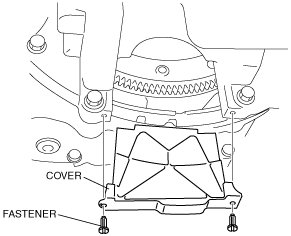
Crankshaft Pulley Lock Bolt Removal Note
1. Remove the cover as shown in the figure.
am6xuw00002061
|
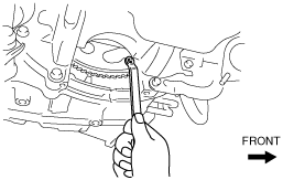
2. Set a wrench to the drive plate bolt at the position shown in the figure to lock the crankshaft rotation.
ac9uuw00000249
|
3. Remove the crankshaft pulley lock bolt and washer.
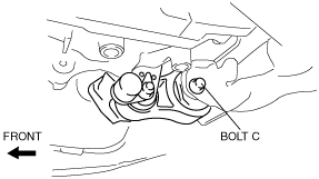
No.3 Engine Mount Removal Note
1. Loosen the No.1 engine mount bolt C.
ac9uuw00003036
|
2. Remove the No.1 engine mounting bracket bolts.
ac9wzw00000697
|
3. Position the coolant reserve tank out of the way. (See COOLANT RESERVE TANK REMOVAL/INSTALLATION [MZI-3.7].)
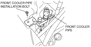
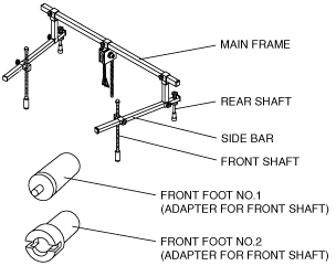
4. Remove the following parts to install the SST.
ac9uuw00002422
|
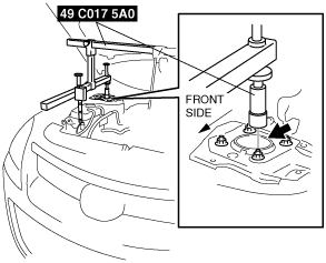
5. Install the SST using the following procedure.
ac9uuw00000021
|
ac9uuw00000185
|
ac9uuw00000186
|
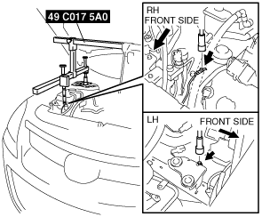
6. Support the engine using the SSTs.
ac9uuw00001874
|
7. Remove the No.3 engine mount.
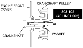
Crankshaft Pulley Removal Note
1. Slightly loosen the SST (49 C017 5A0) support and tilt the engine to the lower side slightly.
2. Remove the washer from the crankshaft pulley lock bolt, install a suitable spacer (thickness: approx. 14 mm {0.55 in}, diameter: approx. 30 mm {1.18 in}), (similar to front shock absorber lower nut) to the crankshaft pulley lock bolt, and install the crankshaft pulley lock bolt to the crankshaft.
ac9uuw00001899
|
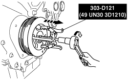
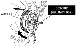
3. Remove the crankshaft pulley using the SST.
ac9uuw00000151
|
4. Remove the crankshaft pulley lock bolt and spacer.
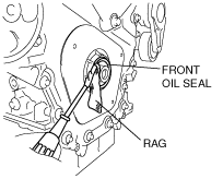
Front Oil Seal Removal Note
1. Remove the front oil seal using a flathead screwdriver as shown.
ac9uuw00000255
|
Front Oil Seal Installation Note
1. Push the front oil seal slightly in by hand.
2. Tap the front oil seal in evenly using the SST and a hammer.
ac9uuw00000600
|
Crankshaft Pulley Installation Note
1. Install the crankshaft pulley, washer, and SST to the crankshaft.
ac9uuw00001884
|
2. Tighten the SST nut and install the crankshaft pulley.
ac9uuw00001900
|
No.3 Engine Mount Installation Note
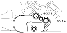
1. Using the SST (49 C017 5A0), tilt up the engine until it is vertical.
2. Tighten the No.1 engine mount bracket bolt A and B in order of A→B.
ac9wzw00000787
|
3. Tighten the No.1 engine mount bolt C at the specified torque.
ac9uuw00003036
|
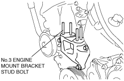
4. Tighten the No.3 engine mount stud bolts.
ac9uuw00003037
|
5. Temporarily tighten the No.3 engine mount bolt and nuts in the order shown in the figure.
ac9uuw00000222
|
6. Tighten the No.3 engine mount in the order shown in the figure.
ac9uuw00000222
|
Tightening Torque
|
Installation Position |
Tightening Torque |
|---|---|
|
1, 2, 7
|
74.5—104.9 N·m {7.60—10.6 kgf·m, 55.0—77.3 ft·lbf}
|
|
3, 4, 5, 6
|
43.1—74 N·m {4.40—7.54 kgf·m, 31.8—54.5 ft·lbf}
|
7. Tighten the No.3 engine mount stay (No.3 engine mount side).
8. Remove the SST (49 C017 5A0).
9. Install the followitng parts.
ac9uuw00000146
|
10. Install the coolant reserve tank. (See COOLANT RESERVE TANK REMOVAL/INSTALLATION [MZI-3.7].)
Crankshaft Pulley Lock Bolt Installation Note
1. Rotate the crankshaft clockwise, and set a wrench to the drive plate bolt at the position shown in the figure to lock the crankshaft rotation.
ac9uuw00000250
|
2. Tighten the new crankshaft pulley lock bolt in 4 steps.
3. Verify the tightening torque for the drive plate installation bolt to which the wrench has been set. (See COOLANT RESERVE TANK REMOVAL/INSTALLATION [MZI-3.7].)
4. Install the cover as shown in the figure.
am6xuw00002061
|