 |
a30zzw00002155
STEERING GEAR AND LINKAGE REMOVAL/INSTALLATION
id061300700800
1. Disconnect the negative lead-acid battery terminal and wait for 1 min or more. (See NEGATIVE LEAD-ACID BATTERY TERMINAL DISCONNECTION/CONNECTION.)
2. Remove the wheel and tire. (See WHEEL AND TIRE REMOVAL/INSTALLATION.)
3. Disconnect the rubber from the front shock absorber.
a30zzw00002155
|
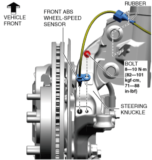
4. Disconnect the front ABS wheel-speed sensor wiring harness on the steering knuckle and set it aside so that it does not interfere with the servicing.
5. Remove the following parts.
6. Remove the front deflector. (See DEFLECTOR REMOVAL/INSTALLATION.)
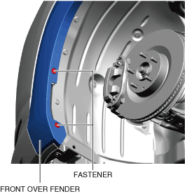
7. Remove the fasteners shown in the figure and slightly bend back the front over fender.
azzjjb00000611
|
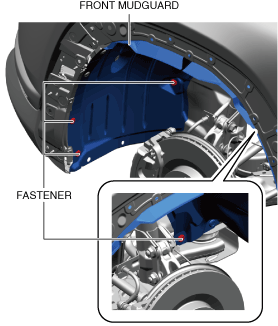
8. Remove the fasteners shown in the figure and slightly bend back the front mudguard.
a30zzw00002156
|
9. Remove the front splash shield. (See SPLASH SHIELD REMOVAL/INSTALLATION.)
10. Disconnect the tie-rod end from the steering knuckle. (See TIE-ROD END REMOVAL/INSTALLATION.)
11. Disconnect the front lower arm ball joint from the steering knuckle. (See FRONT LOWER ARM REMOVAL/INSTALLATION.)
12. Remove the joint cover. (See INTERMEDIATE SHAFT REMOVAL/INSTALLATION.)
13. Disconnect the Intermediate shaft (lower side) from the steering gear and linkage. (See INTERMEDIATE SHAFT REMOVAL/INSTALLATION.)
14. Remove the front crossmember component and No.1 mount rubber as a single unit. (See FRONT CROSSMEMBER REMOVAL/INSTALLATION.)
15. Remove the hole cover No.1 and hole cover No.2. (See FRONT CROSSMEMBER REMOVAL/INSTALLATION.)
16. Remove the Insulator. (R.H.D.) (See Insulator Installation Note.)
a30zzw00006658
|
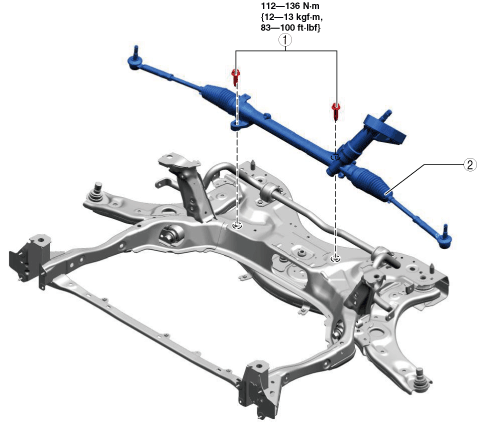
17. Remove in the order shown in the figure.
18. Install in the reverse order of removal.
19. After installation, inspect the front wheel alignment. (See FRONT WHEEL ALIGNMENT.)
a30zzw00002157
|
|
1
|
Steering gear and linkage installation bolt
|
|
2
|
Steering gear and linkage
|
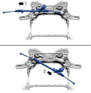
Steering Gear and Linkage Removal Note
1. Move the steering gear and linkage in the direction of the arrow in the order shown in the figure and remove it.
a30zzw00002158
|
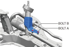
Steering Gear and Linkage Installation Bolt Installation Note
1. Temporarily tighten the steering gear and linkage installation bolts.
a30zzw00002159
|
2. Tighten bolt A.
3. Tighten bolt B.
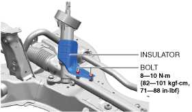
Insulator Installation Note
1. Temporarily tighten bolt A.
a30zzw00006659
|
2. Tighten bolt B.
3. Tighten bolt A.