 |
a30zzw00000792
FRONT CROSSMEMBER REMOVAL/INSTALLATION
id021300701100
1. Remove the wheel and tire. (See WHEEL AND TIRE REMOVAL/INSTALLATION.)
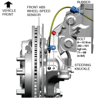
2. Disconnect the rubber from the front shock absorber.
a30zzw00000792
|
3. Disconnect the front ABS wheel-speed sensor wiring harness on the steering knuckle and set it aside so that it does not interfere with the servicing.
4. Remove the following parts.
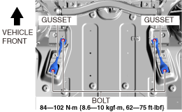
5. Remove the gusset. (See Gusset Installation Note.)
a30zzw00000009
|
6. Remove the floor under cover No.1. (See FLOOR UNDER COVER REMOVAL/INSTALLATION.)
7. Remove the guard component. (See GUARD COMPONENT REMOVAL/INSTALLATION.)
8. Disconnect the tie-rod end from the steering knuckle. (See TIE-ROD END REMOVAL/INSTALLATION.)
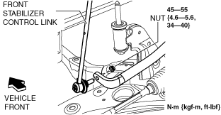
9. Disconnect the front stabilizer control link (front stabilizer side).
ac8wzw00001906
|
10. Disconnect the front lower arm ball joint from the steering knuckle. (See FRONT LOWER ARM REMOVAL/INSTALLATION.)
11. Remove the front deflector. (See DEFLECTOR REMOVAL/INSTALLATION.)
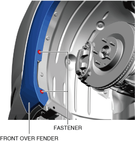
12. Remove the fasteners shown in the figure and slightly bend back the front over fender.
a30zzw00001714
|
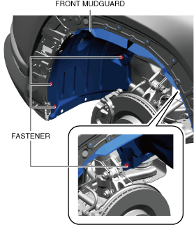
13. Remove the fasteners shown in the figure and slightly bend back the front mudguard.
a30zzw00001715
|
14. Remove the front splash shield. (See SPLASH SHIELD REMOVAL/INSTALLATION.)
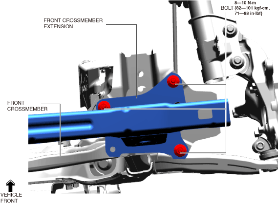
15. Disconnect the front crossmember extension.
a30zzw00000010
|
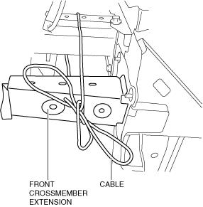
16. Suspend the front crossmember extension using a cable.
am3zzw00023031
|
17. Remove the joint cover. (See INTERMEDIATE SHAFT REMOVAL/INSTALLATION.)
18. Disconnect the Intermediate shaft (lower side) from the steering gear and linkage. (See INTERMEDIATE SHAFT REMOVAL/INSTALLATION.)
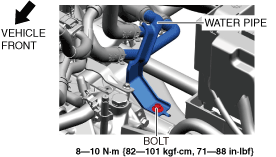
19. Remove the bolt shown in the figure.
a30zzw00000848
|
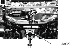
20. Support the front crossmember component using a jack.
a30zzw00001722
|
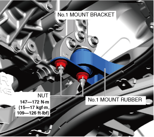
21. Remove the nuts shown in the figure. (See Front Crossmember Component Installation Note.) (See No.1 Mount, Front Crossmember Component Installation Note.)
a30zzw00000793
|
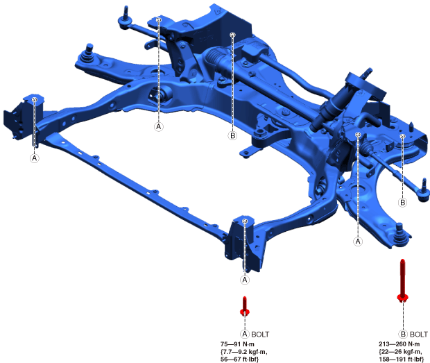
22. Remove the bolts shown in the figure. (See Front Crossmember Component Installation Note.) (See No.1 Mount, Front Crossmember Component Installation Note.)
a30zzw00001716
|
23. Remove the front crossmember component. (See Front Crossmember Component Installation Note.)
a30zzw00000794
|
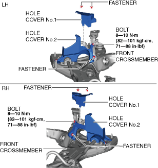
24. Remove the hole cover No.1 and hole cover No.2.
am3zzw00027646
|
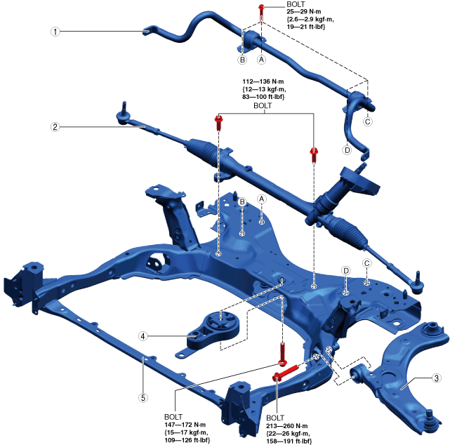
25. Remove in the order shown in the figure.
26. Install in the reverse order of removal. (See Suspension Links Installation Note.)
27. If the front crossmember is replaced, inspect the wheel alignment and adjust it if necessary. (See FRONT WHEEL ALIGNMENT.)
a30zzw00000795
|
|
1
|
Front stabilizer component
(See FRONT STABILIZER REMOVAL.)
|
|
2
|
Steering gear and linkage
|
|
3
|
Front lower arm
|
|
4
|
No.1 mount rubber (See No.1 Mount, Front Crossmember Component Installation Note.)
|
|
5
|
Front crossmember (See Front Crossmember Component Installation Note.) (See No.1 Mount, Front Crossmember Component Installation Note.)
|
Suspension Links Installation Note
1. When installing the joint sections with rubber bushings, perform the following procedures.
Front Crossmember Component Installation Note
am3zzw00023035
|
No.1 Mount, Front Crossmember Component Installation Note
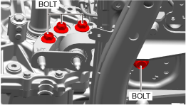
1. Temporarily tighten the bolts shown in the figure.
a30zzw00001717
|
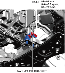
2. Tighten the bolts shown in the figure.
a30zzw00001718
|
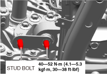
3. Tighten the stud bolts shown in the figure.
a30zzw00001719
|
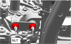
4. Temporarily tighten the nuts shown in the figure.
a30zzw00001720
|
5. Tighten the nuts shown in the figure.
a30zzw00001720
|
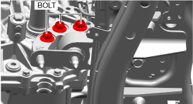
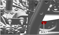
6. Tighten the bolts shown in the figure.
a30zzw00001721
|
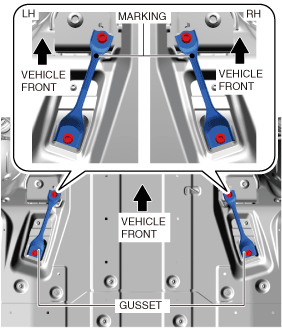
Gusset Installation Note
1. When installing the gussets to the vehicle, install them as shown in the figure.
a30zzw00002193
|