|
1
|
VERIFY DASH-ELECTRICAL SUPPLY UNIT DTCs
• Perform the DTC inspection for the dash-electrical supply unit using the M-MDS.
• Is a DTC displayed?
|
Yes
|
Repair the malfunctioning part according to the applicable DTC troubleshooting and perform the repair completion verification.
|
|
No
|
Go to the next step.
|
|
2
|
VERIFY BLOWER MOTOR OPERATION
• Switch the main power ON (READY off or on).
• Set the airflow volume control switch to ON.
• Set the air intake mode to REC.
• Does the blower motor in the blower unit rotate smoothly?
|
Yes
|
Go to the next step.
|
|
No
|
Go to Step 4.
|
|
3
|
INSPECT BLOWER UNIT FOR CLOGGING
• Is there clogging in the vent of the blower unit?
|
Yes
|
Remove the obstruction, then go to the repair completion verification.
|
|
No
|
Verify that there is no obstruction in the air duct between the blower unit and A/C unit, there is no air filter clogging, and the evaporator is not frosted (frozen), then go to the repair completion verification.
|
|
4*
|
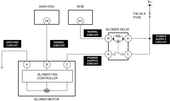
VERIFY BLOWER MOTOR TERMINAL VOLTAGE
• Switch the main power ON (READY off or on).
• Set the airflow volume control dial to 6 or more.
• Measure the voltage at the following terminals.
-
― Blower motor terminal C
• Is the voltage B+?
|
Yes
|
Go to the next step.
|
|
No
|
Go to Step 10.
|
|
5
|
VERIFY F40 40A FUSE
• Remove the F40 40A fuse.
• Inspect the F40 40A fuse.
• Is the fuse normal?
|
Yes
|
Install the F40 40A fuse, then go to the next step.
|
|
No
|
Replace the F40 40A fuse and perform the repair completion verification.
|
|
6*
|
VERIFY BLOWER RELAY TERMINAL VOLTAGE
• Measure the voltage at the following terminals.
-
― Blower relay terminal C
― Blower relay terminal D
• Is the voltage B+?
|
Yes
|
Go to the next step.
|
|
No
|
Repair or replace the blower relay power supply circuit and perform the repair completion verification.
|
|
7*
|
VERIFY BLOWER RELAY TERMINAL VOLTAGE
• Measure the voltage at the following terminals.
-
― Blower relay terminal B
• Is the voltage 0 V?
|
Yes
|
Go to the next step.
|
|
No
|
Go to Step 9.
|
|
8*
|
VERIFY BODY CONTROL MODULE (BCM) TERMINAL VOLTAGE
• Measure the voltage at the following terminals.
-
― Body control module (BCM) terminal 2O
• Is the voltage 0 V?
|
Yes
|
Repair or replace the body control module (BCM) signal circuit and perform the repair completion verification.
|
|
No
|
Replace the body control module (BCM) and perform the repair completion verification.
|
|
9*
|
VERIFY BLOWER RELAY TERMINAL VOLTAGE
• Measure the voltage at the following terminals.
-
― Blower relay terminal A
• Is the voltage B+?
|
Yes
|
After replacing the blower relay, perform the repair completion verification.
|
|
No
|
Repair or replace the blower motor power supply circuit and perform the repair completion verification.
|
|
10
|
INSPECT BLOWER MOTOR
• Inspect the applicable parts.
• Is the blower motor normal?
|
Yes
|
Go to the next step.
|
|
No
|
After replacing the blower motor, perform the repair completion verification.
|
|
11
|
INSPECT BLOWER MOTOR SIGNAL CIRCUIT FOR OPEN CIRCUIT AND SHORT TO GROUND
• Inspect the applicable circuit for an open circuit and short to ground.
• Is the circuit normal?
|
Yes
|
Go to the next step.
|
|
No
|
Repair or replace the malfunctioning part and perform the repair completion verification.
|
|
12
|
INSPECT BLOWER MOTOR GROUND CIRCUIT FOR OPEN CIRCUIT AND SHORT TO POWER SUPPLY
• Inspect the applicable circuit for an open circuit and short to power supply.
• Is the circuit normal?
|
Yes
|
Go to the next step.
|
|
No
|
Repair or replace the malfunctioning part and perform the repair completion verification.
|
|
13
|
VERIFY IF THERE IS OBSTRUCTION IN BLOWER MOTOR FAN ROTATION
• Inspect the blower motor fan in the blower unit.
-
― Is the fan free of interference with the blower unit case?
― Is the fan free of foreign matter and obstructions?
• Is the blower motor fan normal?
|
Yes
|
Replace the dash-electrical supply unit and perform the repair completion verification.
|
|
No
|
Remove the obstruction or repair/replace the blower motor fan, blower unit case, and perform the repair completion verification.
|
|
Repair completion verification
|
VERIFY THAT MALFUNCTION DOES NOT RECUR AFTER REPAIRS
• Install/connect the part removed/disconnected during the troubleshooting procedure.
• Has the malfunction symptom been eliminated?
|
Yes
|
Troubleshooting completed. (Explain repair contents to customer.)
|
|
No
|
Refer to the controller area network (CAN) malfunction diagnosis flow to inspect for a CAN communication error.
If the CAN communication is normal, perform the diagnosis from Step 1.
• If the malfunction is not resolved, replace the dash-electrical supply unit.
|