SHOCK ABSORBING PAD REMOVAL/INSTALLATION
id091700605800
5HB
Front
1. Disconnect the negative battery cable. (See NEGATIVE BATTERY CABLE DISCONNECTION/CONNECTION.)
2. Remove the following parts:
- (1) A-pillar trim (See A-PILLAR TRIM REMOVAL/INSTALLATION.)
- (2) Sunvisor (See SUNVISOR REMOVAL/INSTALLATION.)
- (3) Front map light (dual light type) (See FRONT MAP LIGHT REMOVAL/INSTALLATION.)
- (4) Assist handle (See ASSIST HANDLE REMOVAL/INSTALLATION.)
- (5) Coat hook (See HEADLINER REMOVAL/INSTALLATION.)
- (6) Front scuff plate (See FRONT SCUFF PLATE REMOVAL/INSTALLATION.)
- (7) Rear scuff plate (See REAR SCUFF PLATE REMOVAL/INSTALLATION.)
- (8) B-pillar lower trim (See B-PILLAR LOWER TRIM REMOVAL/INSTALLATION.)
- (9) Adjust anchor cover (See FRONT SEAT BELT REMOVAL/INSTALLATION.)
- (10) Upper anchor installation bolt on the seat belt (See FRONT SEAT BELT REMOVAL/INSTALLATION.)
- (11) B-pillar upper trim (See B-PILLAR UPPER TRIM REMOVAL/INSTALLATION.)
- (12) Rear seat cushion (See REAR SEAT CUSHION REMOVAL/INSTALLATION.)
- (13) Lower anchor installation bolt on the rear center seat belt (See REAR CENTER SEAT BELT REMOVAL/INSTALLATION.)
- (14) Rear seat back (See REAR SEAT BACK REMOVAL/INSTALLATION.)
- (15) Rear package tray (See REAR PACKAGE TRAY REMOVAL/INSTALLATION.)
- (16) Trunk covering (See TRUNK COVERING REMOVAL/INSTALLATION.)
- (17) Trunk board (See TRUNK BOARD REMOVAL/INSTALLATION.)
- (18) Trunk end trim (See TRUNK END TRIM REMOVAL/INSTALLATION.)
- (19) Trunk side trim (See TRUNK SIDE TRIM REMOVAL/INSTALLATION.)
- (20) C-pillar trim (See C-PILLAR TRIM REMOVAL/INSTALLATION.)
- (21) Headliner (See HEADLINER REMOVAL/INSTALLATION.)
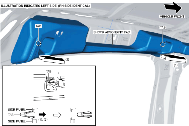
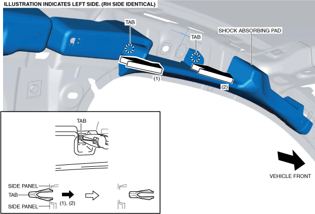
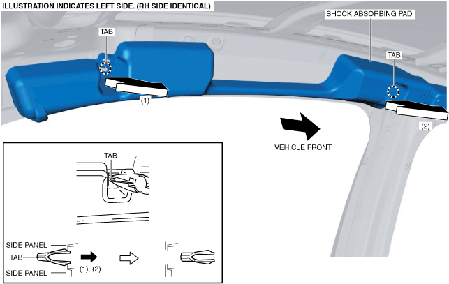
3. While holding the tabs of the shock absorbing pad using pincers, pull the tabs in the direction of arrow (1) shown in the figure and detach the tabs from the side panel.
4. While holding the tabs of the shock absorbing pad using pincers, pull the tabs in the direction of arrow (2) shown in the figure and detach the tabs from the side panel.
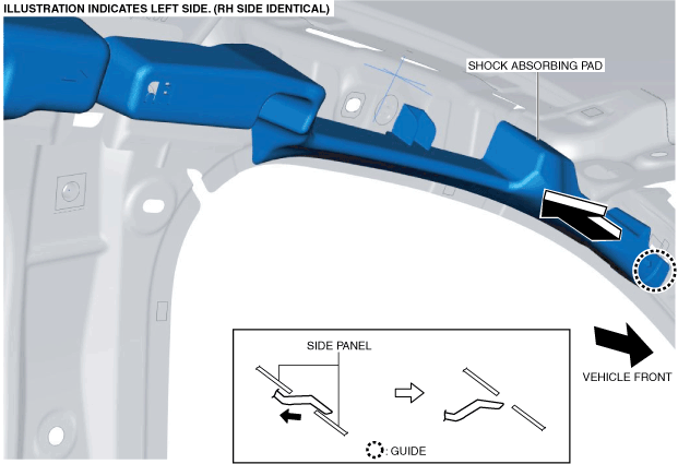
5. Pull the shock absorbing pad in the direction of the arrow and remove it while detaching the guide.
6. Install in the reverse order of removal.
Rear
1. Disconnect the negative battery cable. (See NEGATIVE BATTERY CABLE DISCONNECTION/CONNECTION.)
2. Remove the following parts:
- (1) A-pillar trim (See A-PILLAR TRIM REMOVAL/INSTALLATION.)
- (2) Sunvisor (See SUNVISOR REMOVAL/INSTALLATION.)
- (3) Front map light (dual light type) (See FRONT MAP LIGHT REMOVAL/INSTALLATION.)
- (4) Assist handle (See ASSIST HANDLE REMOVAL/INSTALLATION.)
- (5) Coat hook (See HEADLINER REMOVAL/INSTALLATION.)
- (6) Front scuff plate (See FRONT SCUFF PLATE REMOVAL/INSTALLATION.)
- (7) Rear scuff plate (See REAR SCUFF PLATE REMOVAL/INSTALLATION.)
- (8) B-pillar lower trim (See B-PILLAR LOWER TRIM REMOVAL/INSTALLATION.)
- (9) Adjust anchor cover (See FRONT SEAT BELT REMOVAL/INSTALLATION.)
- (10) Upper anchor installation bolt on the seat belt (See FRONT SEAT BELT REMOVAL/INSTALLATION.)
- (11) B-pillar upper trim (See B-PILLAR UPPER TRIM REMOVAL/INSTALLATION.)
- (12) Rear seat cushion (See REAR SEAT CUSHION REMOVAL/INSTALLATION.)
- (13) Lower anchor installation bolt on the rear center seat belt (See REAR CENTER SEAT BELT REMOVAL/INSTALLATION.)
- (14) Rear seat back (See REAR SEAT BACK REMOVAL/INSTALLATION.)
- (15) Rear package tray (See REAR PACKAGE TRAY REMOVAL/INSTALLATION.)
- (16) Trunk covering (See TRUNK COVERING REMOVAL/INSTALLATION.)
- (17) Trunk board (See TRUNK BOARD REMOVAL/INSTALLATION.)
- (18) Trunk end trim (See TRUNK END TRIM REMOVAL/INSTALLATION.)
- (19) Trunk side trim (See TRUNK SIDE TRIM REMOVAL/INSTALLATION.)
- (20) C-pillar trim (See C-PILLAR TRIM REMOVAL/INSTALLATION.)
- (21) Headliner (See HEADLINER REMOVAL/INSTALLATION.)
3. While holding the tabs of the shock absorbing pad using pincers, pull the tabs in the direction of arrow (1) shown in the figure and detach the tabs from the side panel.
4. While holding the tabs of the shock absorbing pad using pincers, pull the tabs in the direction of arrow (2) shown in the figure and detach the tabs from the side panel.
5. Install in the reverse order of removal.
4SD
Front
1. Disconnect the negative battery cable. (See NEGATIVE BATTERY CABLE DISCONNECTION/CONNECTION.)
2. Remove the following parts:
- (1) A-pillar trim (See A-PILLAR TRIM REMOVAL/INSTALLATION.)
- (2) Sunvisor (See SUNVISOR REMOVAL/INSTALLATION.)
- (3) Front map light (dual light type) (See FRONT MAP LIGHT REMOVAL/INSTALLATION.)
- (4) Assist handle (See ASSIST HANDLE REMOVAL/INSTALLATION.)
- (5) Coat hook (See HEADLINER REMOVAL/INSTALLATION.)
- (6) Center console tray (See CENTER CONSOLE TRAY REMOVAL/INSTALLATION.)
- (7) Shift bezel (See SHIFT BEZEL REMOVAL/INSTALLATION.)
- (8) Upper panel (See UPPER PANEL REMOVAL/INSTALLATION.)
- (9) Shift lever knob (MTX) (See MANUAL TRANSAXLE SHIFT MECHANISM REMOVAL/INSTALLATION [F65M-R].) (See MANUAL TRANSAXLE SHIFT MECHANISM REMOVAL/INSTALLATION [F66M-R].)
- (10) Selector lever knob (ATX) (See AUTOMATIC TRANSAXLE SHIFT MECHANISM REMOVAL/INSTALLATION.)
- (11) Shift panel (See SHIFT PANEL REMOVAL/INSTALLATION.)
- (12) Console side panel (See CONSOLE SIDE PANEL REMOVAL/INSTALLATION.)
- (13) Front console box (See FRONT CONSOLE BOX REMOVAL/INSTALLATION.)
- (14) CD player (with CD player) (See CD PLAYER REMOVAL.) (See CD PLAYER INSTALLATION.)
- (15) DVD/CD player (with DVD/CD player) (See DVD/CD PLAYER REMOVAL.) (See DVD/CD PLAYER INSTALLATION.)
- (16) Front console (See FRONT CONSOLE REMOVAL/INSTALLATION.)
- (17) Side wall (See SIDE WALL REMOVAL/INSTALLATION.)
- (18) Rear console (See REAR CONSOLE REMOVAL/INSTALLATION.)
- (19) Front scuff plate (See FRONT SCUFF PLATE REMOVAL/INSTALLATION.)
- (20) Rear scuff plate (See REAR SCUFF PLATE REMOVAL/INSTALLATION.)
- (21) B-pillar lower trim (See B-PILLAR LOWER TRIM REMOVAL/INSTALLATION.)
- (22) Adjust anchor cover (See FRONT SEAT BELT REMOVAL/INSTALLATION.)
- (23) Upper anchor installation bolt on the seat belt (See FRONT SEAT BELT REMOVAL/INSTALLATION.)
- (24) B-pillar upper trim (See B-PILLAR UPPER TRIM REMOVAL/INSTALLATION.)
- (25) C-pillar trim (See C-PILLAR TRIM REMOVAL/INSTALLATION.)
- (26) Headliner (See HEADLINER REMOVAL/INSTALLATION.)
3. While holding the tabs of the shock absorbing pad using pincers, pull the tabs in the direction of arrow (1) shown in the figure and detach the tabs from the side panel.
4. While holding the tabs of the shock absorbing pad using pincers, pull the tabs in the direction of arrow (2) shown in the figure and detach the tabs from the side panel.
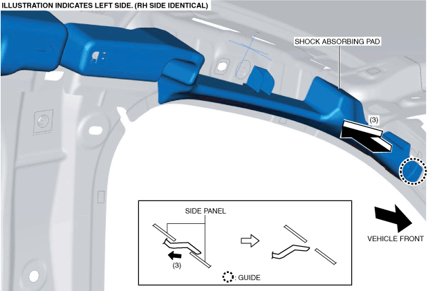
5. Pull the shock absorbing pad in the direction of the arrow (3) and remove it while detaching guide.
6. Install in the reverse order of removal.
Rear
1. Disconnect the negative battery cable. (See NEGATIVE BATTERY CABLE DISCONNECTION/CONNECTION.)
2. Remove the following parts:
- (1) A-pillar trim (See A-PILLAR TRIM REMOVAL/INSTALLATION.)
- (2) Sunvisor (See SUNVISOR REMOVAL/INSTALLATION.)
- (3) Front map light (dual light type) (See FRONT MAP LIGHT REMOVAL/INSTALLATION.)
- (4) Assist handle (See ASSIST HANDLE REMOVAL/INSTALLATION.)
- (5) Coat hook (See HEADLINER REMOVAL/INSTALLATION.)
- (6) Center console tray (See CENTER CONSOLE TRAY REMOVAL/INSTALLATION.)
- (7) Shift bezel (See SHIFT BEZEL REMOVAL/INSTALLATION.)
- (8) Upper panel (See UPPER PANEL REMOVAL/INSTALLATION.)
- (9) Shift lever knob (MTX) (See MANUAL TRANSAXLE SHIFT MECHANISM REMOVAL/INSTALLATION [F65M-R].) (See MANUAL TRANSAXLE SHIFT MECHANISM REMOVAL/INSTALLATION [F66M-R].)
- (10) Selector lever knob (ATX) (See AUTOMATIC TRANSAXLE SHIFT MECHANISM REMOVAL/INSTALLATION.)
- (11) Shift panel (See SHIFT PANEL REMOVAL/INSTALLATION.)
- (12) Console side panel (See CONSOLE SIDE PANEL REMOVAL/INSTALLATION.)
- (13) Front console box (See FRONT CONSOLE BOX REMOVAL/INSTALLATION.)
- (14) CD player (with CD player) (See CD PLAYER REMOVAL.) (See CD PLAYER INSTALLATION.)
- (15) DVD/CD player (with DVD/CD player) (See DVD/CD PLAYER REMOVAL.) (See DVD/CD PLAYER INSTALLATION.)
- (16) Front console (See FRONT CONSOLE REMOVAL/INSTALLATION.)
- (17) Side wall (See SIDE WALL REMOVAL/INSTALLATION.)
- (18) Rear console (See REAR CONSOLE REMOVAL/INSTALLATION.)
- (19) Front scuff plate (See FRONT SCUFF PLATE REMOVAL/INSTALLATION.)
- (20) Rear scuff plate (See REAR SCUFF PLATE REMOVAL/INSTALLATION.)
- (21) B-pillar lower trim (See B-PILLAR LOWER TRIM REMOVAL/INSTALLATION.)
- (22) Adjust anchor cover (See FRONT SEAT BELT REMOVAL/INSTALLATION.)
- (23) Upper anchor installation bolt on the seat belt (See FRONT SEAT BELT REMOVAL/INSTALLATION.)
- (24) B-pillar upper trim (See B-PILLAR UPPER TRIM REMOVAL/INSTALLATION.)
- (25) C-pillar trim (See C-PILLAR TRIM REMOVAL/INSTALLATION.)
- (26) Headliner (See HEADLINER REMOVAL/INSTALLATION.)
3. While holding the tabs of the shock absorbing pad using pincers, pull the tabs in the direction of arrow (1) shown in the figure and detach the tabs from the side panel.
4. While holding the tabs of the shock absorbing pad using pincers, pull the tabs in the direction of arrow (2) shown in the figure and detach the tabs from the side panel.
5. Install in the reverse order of removal.