 |
am2zzw00001045
EXPANSION VALVE INSTALLATION
id071100817200
L.H.D.
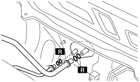
1. Slide the outlet pipe to the right while being careful not to allow the remaining compressor oil in the outlet pipe to spill.
am2zzw00001045
|
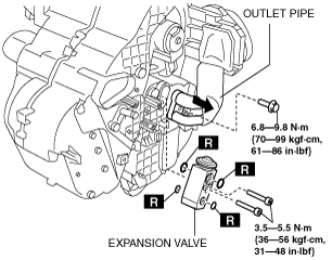
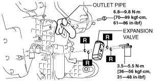
2. Install the expansion valve.
3. Install the outlet pipe.
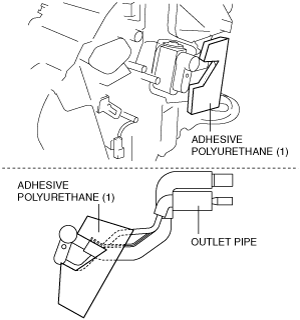
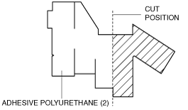
4. Cut the adhesive polyurethane (1) as shown in the figure.
am2zzw00001046
|
5. Attach the adhesive polyurethane (1) to the outlet pipe as shown in the figure.
am2zzw00001047
|
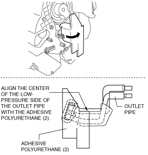
6. Roll the adhesive polyurethane (1) around the outlet pipe.
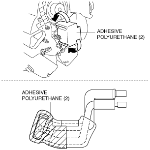
7. Align the adhesive polyurethane (2) notch with the center of the lower surface of the expansion valve, and adhere.
am2zzw00002013
|
8. Roll on the adhesive polyurethane (2) so that it wraps around the expansion valve.
am2zzw00001023
|
9. Bend around the adhesive polyurethane (2) and adhere it to the outlet pipe.
am2zzw00001024
|
10. Connect the power MOS FET connector. (full-auto air conditioner)
11. Connect the resistor connector. (manual air conditioner)
12. Install the evaporator temperature sensor wiring harness clip.
13. Connect the evaporator temperature sensor connector.
14. Install the following parts:
15. Connect the clutch pipe and cooler hose while being careful not to allow the remaining oil in the pipe and A/C unit to spill. (See REFRIGERANT LINE REMOVAL/INSTALLATION.)
adejjw00002606
|
16. Install the cooler hose (LO) bracket.
adejjw00002625
|
17. Install the air cleaner component.
18. Charge the refrigerant. (See REFRIGERANT CHARGING.)
19. Connect the negative battery cable.
20. Perform the refrigerant system performance test. (See REFRIGERANT SYSTEM PERFORMANCE TEST.)
R.H.D.
1. Slide the outlet pipe to the right while being careful not to allow the remaining compressor oil in the outlet pipe to spill.
adejjw00002600
|
2. Install the expansion valve.
3. Install the outlet pipe.
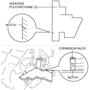
4. Cut the adhesive polyurethane (2) as shown in the figure.
am2zzw00001875
|
5. Align the adhesive polyurethane (2) notch with the center of the lower surface of the expansion valve, and adhere.
am2zzw00002019
|
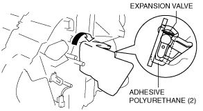
6. Roll on the adhesive polyurethane (2) so that it wraps around the expansion valve.
adejjw00002603
|
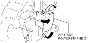
7. Bend around the adhesive polyurethane (2) and adhere it to the side surface of the outlet pipe.
am2zzw00002020
|
8. Roll the adhesive polyurethane (2) on to the outlet pipe as shown in the figure.
am2zzw00001876
|
9. Instal the air mix actuator. (full-auto air conditioner) (See AIR MIX ACTUATOR REMOVAL/INSTALLATION [FULL-AUTO AIR CONDITIONER].)
10. Install the clutch pedal. (MTX) (See CLUTCH PEDAL REMOVAL/INSTALLATION [F35M-R].) (See CLUTCH PEDAL REMOVAL/INSTALLATION [B65M-R].)
11. Install the following parts:
12. Connect the cooler pipe and cooler hose while being careful not to allow the remaining oil in the pipe and A/C unit to spill. (See REFRIGERANT LINE REMOVAL/INSTALLATION.)
adejjw00002606
|
13. Install the cooler hose (LO) bracket.
adejjw00002625
|
14. Install the air cleaner component.
15. Charge the refrigerant. (See REFRIGERANT CHARGING.)
16. Connect the negative battery cable.
17. Perform the refrigerant system performance test. (See REFRIGERANT SYSTEM PERFORMANCE TEST.)