STEP
INSPECTION
ACTION
1
INSPECT BRAKE FLUID AMOUNT AND VERIFY THAT PARKING BRAKE RELEASES
• Is the brake fluid amount normal?
• Is the parking brake lever released?
Yes
MZR 1.3, MZR 1.5 with malfunction warning light
Go to step 3.
MZR 1.3, MZR 1.5 without malfunction warning light
Go to the next step.
MZ-CD 1.6
Go to step 3.
No
Add brake fluid or release the parking brake lever.
2
INSPECT PCM DTC
• Retrieve the PCM DTC using the M-MDS.
• Is the DTC P0571:00 and/or P0703:00 present?
Yes
Go to the applicable DTC inspection.
No
Go to the next step.
3
INSPECT FOR DTCS IN DSC
• Retrieve DSC DTC using the M-MDS.
• Is there any DSC DTC displayed?
Yes
Go to applicable DTC troubleshooting procedure.
No
Go to the next step.
4
INSPECT DTCS IN INSTRUMENT CLUSTER
• Retrieve instrument cluster DTC using the M-MDS.
• Is DTC U0415:92 displayed?
Yes
Go to the next step.
No
Go to Step 7.
5*
INSPECT DSC CM POWER SUPPLY VOLTAGE
• Monitor PID VPWR using the M-MDS data monitor function.
• Is the monitoring value above 10 V?
Yes
DSC CM internal malfunctions.
Replace the DSC CM.
No
Go to the next step.
6
INSPECT WHETHER MALFUNCTION IS IN INSTRUMENT CLUSTER OR ELSEWHERE
• Release the parking brake.
• Turn off all warning light and indicator light using M-MDS simulation function WL+IL?
• Does the DSC warning light turn off?
Yes
Go to the next step.
No
Replace the instrument cluster.
7
INSPECT FOR CONNECTION OF DSC HU/CM CONNECTOR
• Is the DSC HU/CM connector connected securely?
Yes
Go to Step 9.
No
Connect the connector securely, then go to the next step.
8
VERIFY DSC WARNING LIGHT OPERATION
• Turn the ignition switch to ON position.
• Does the DSC warning light turn off 4 seconds after the ignition switch is ON position?
Yes
Troubleshooting is completed. (DSC HU/CM connector is not connected securely.)
No
Go to the next step.
9
INSPECT BATTERY VOLTAGE
• Inspect battery voltage.
• Is the battery voltage normal?
Yes
Go to the next step.
No
Inspect charging system.
Replace the battery if necessary.
10
INSPECT BATTERY VOLTAGE WHILE ELECTRICAL LOAD IS OPERATING
• Inspect the battery voltage while electrical load (A/C, headlight etc.) is operating.
• Is the battery voltage normal?
Yes
Inspect wiring harness in DSC HU/CM terminal Y and terminal B related circuit.
No
Go to the next step.
11
INSPECT CHARGING SYSTEM
• Inspect the battery voltage normal with electrical load (such as, A/C headlight) on the engine idling?
Yes
Go to the next step.
No
Inspect the charging system (such as drive belt tension, generator).
12
INSPECT WTHERE MALFUNCTION IS IN BRAKE SYSTEM WARNING LIGHT RELATED SWITCHES OR ELSE WHERE
• Inspect following parts for continuity.
-
― Parking brake switch― Brake fluid level sensor
• Is the continuity condition normal?
Yes
Go to the next step.
No
Repair or replace malfunctioning part.
13
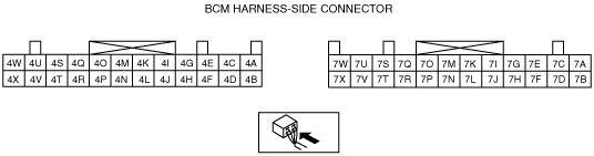
INSPECT FOR SHORT TO GND CIRCUIT IN WIRING BETWEEN BCM AND BRAKE SYSTEM WARNING LIGHT RELATED SWITCHES
• Inspect for open circuit in wiring for following:
-
― Between parking switch and BCM terminal 7B― Between brake fluid level sensor and BCM terminal 4A
• Is the short to GND circuit detected?
Yes
Repair or replace malfunctioning part.
No
Replace the BCM.