DTC P0504 [MZ-CD 1.6 (Y6) (EURO4 emission level)]
id0102g6832500
Applied VIN (assumed): JMZ BL1*Y20# 100001—151064
DTC P0504 |
Brake switch and brake pedal position signal not plausible |
---|---|
DETECTION CONDITION
|
• The PCM monitors and compares changes in the input signal for the brake switch and brake pedal position signal (from instrument cluster). If the PCM detects any of the following conditions, the PCM determines that the brake switch and brake pedal position signal have a compatibility malfunction.
|
POSSIBLE CAUSE
|
• Communication error between instrument cluster and PCM
• Brake switch and/or BPP switch improper installation
• Brake switch malfunction
• Open or short circuit in wiring harness between brake switch and ground through brake light
• Open or short circuit in wiring harness between brake switch and PCM terminal 317
• Brake pedal position (BPP) switch malfunction
• Open or short circuit in wiring harness between brake pedal position switch and instrument cluster terminal 2N
• Open circuit in wiring harness between brake pedal position switch and body ground
• Instrument cluster malfunction
• PCM malfunction
|
![]() |
Diagnostic procedure
STEP |
INSPECTION |
ACTION |
|
---|---|---|---|
1
|
VERIFY FREEZE FRAME DATA HAS BEEN RECORDED
• Has the FREEZE FRAME DATA been recorded?
|
Yes
|
Go to the next step.
|
No
|
Record the FREEZE FRAME DATA on the repair order, then go to the next step.
|
||
2
|
VERIFY RELATED REPAIR INFORMATION AVAILABILITY
• Verify related service repair information availability.
• Is any related repair information available?
|
Yes
|
Perform repair or diagnosis according to the available repair information.
• If the vehicle is not repaired, go to the next step.
|
No
|
Go to the next step.
|
||
3
|
VERIFY STORED CAN COMMUNICATION DTC IN PCM AND INSTRUMENT CLUSTER
• Retrieve the PCM and instrument cluster DTC using the M-MDS.
• Is the CAN communication DTC present?
|
Yes
|
Go to the applicable DTC inspection.
|
No
|
Go to the next step.
|
||
4
|
INSPECT BRAKE SWITCH AND BRAKE PEDAL POSITION (BPP) SWITCH POOR INSTALLATION
• Inspect the brake switch and BPP switch for installation.
• Are there installed properly?
|
Yes
|
Go to the next step.
|
No
|
Install the brake switch properly, then go to Step 12.
|
||
5
|
INSPECT BRAKE SWITCH AND BRAKE PEDAL POSITION (BPP) SWITCH CONNECTORS CONDITION
• Switch the ignition to off.
• Disconnect the brake switch and BPP switch connector.
• Inspect for poor connection (such as damaged/pulled-out pins, corrosion).
• Is there any malfunction?
|
Yes
|
Repair or replace the connector and/or terminals, then go to Step 12.
|
No
|
Go to the next step.
|
||
6
|
VERIFY STOP LIGHT OPERATION
• Verify the stop light operation.
• Is the stop light turn on and off according to brake pedal conditions?
|
Yes
|
Go to Step 9.
|
No
|
Stop light is always on
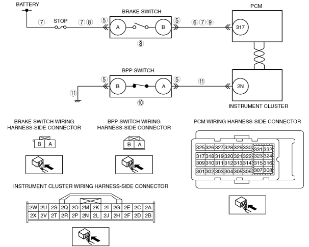
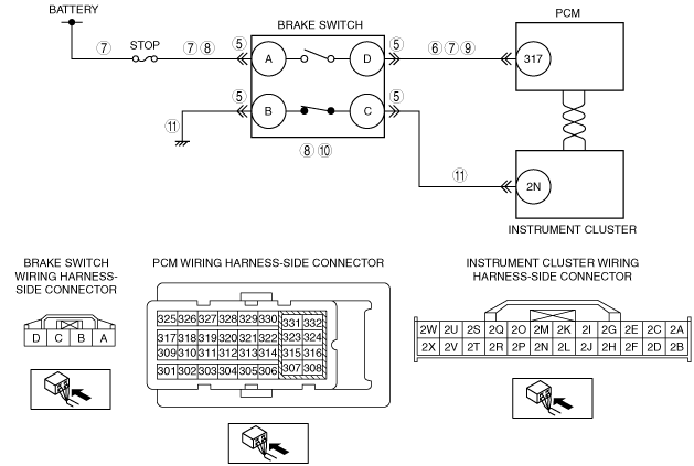
• Repair or replace for a possible short to power supply between brake switch terminal B and PCM terminal 317, then go to Step 12.
Stop light is always off, go to the next step.
|
||
7
|
VERIFY STOP FUSE CONDITION
• Verify the STOP fuse condition.
• Is the STOP fuse normal?
|
Yes
|
Go to the next step.
|
No
|
If the fuse is blown:
• Repair for short to ground in following wiring harness:
• If the fuse is deterioration:
Then go to Step 12.
|
||
8
|
VERIFY WHETHER MALFUNCTION IS BRAKE SWITCH OR OPEN CIRCUIT
• Inspect the brake switch.
(See BRAKE SWITCH INSPECTION.)
• Is there any malfunction?
|
Yes
|
Replace the brake switch, then go to Step 12.
|
No
|
Repair for a possible open circuit between brake switch terminal A and STOP fuse, then go to Step 12.
|
||
9
|
INSPECT BRAKE SWITCH SIGNAL CIRCUIT FOR OPEN
• Measure the voltage between PCM terminal 317 (wiring harness-side) and body ground.
• Is the voltage normal?
|
Yes
|
Go to the next step.
|
No
|
Repair for a possible open circuit between brake switch terminal B and PCM terminal 317, then go to Step 12.
|
||
10
|
INSPECT BRAKE PEDAL POSITION (BPP) SWITCH
• Inspect the BPP switch.
• Is there any malfunction?
|
Yes
|
Replace the BPP switch, then go to Step 12.
|
No
|
Go to the next step.
|
||
11
|
VERIFY WHETHER MALFUNCTION IS INSTRUMENT CLUSTER OR BPP SWITCH HARNESSES
• Measure the voltage between instrument cluster terminal 2N (wiring harness-side) and body ground.
• Is the voltage normal?
|
Yes
|
Replace the instrument cluster, then go to the next step.
(Instrument cluster can not transmit BPP signal to PCM)
|
No
|
Repair for a possible open or short circuit between following, then go to the next step.
• BPP switch terminal A and instrument cluster terminal 2N
• BPP switch terminal B and body ground
|
||
12
|
VERIFY THAT DTC P0504 TROUBLESHOOTING IS COMPLETED
• Make sure to reconnect all disconnected connectors.
• Clear the DTC from the PCM memory using the M-MDS.
• Run the vehicle under the FREEZE FRAME DATA stored condition.
• Is the same DTC present?
|
Yes
|
Repeat the inspection from Step 1.
• If the malfunction recurs, replace the PCM.
Go to the next step.
|
No
|
Go to the next step.
|
||
13
|
VERIFY AFTER REPAIR PROCEDURE
• Perform the after repair procedure.
• Are any DTCs present?
|
Yes
|
Go to the applicable DTC inspection.
|
No
|
DTC troubleshooting completed.
|
Applied VIN (assumed): JMZ BL1*Y20# 151065—
DTC P0504 |
Brake switch signal not plausible |
---|---|
DETECTION CONDITION
|
• The PCM monitors and compares changes in the input signal for the brake switch and brake pedal position signal (from instrument cluster). If the PCM detects any of the following conditions, the PCM determines that the brake switch and brake pedal position signal have a compatibility malfunction.
|
POSSIBLE CAUSE
|
• Communication error between instrument cluster and PCM
• Brake switch improper installation
• Brake switch malfunction
• Open or short circuit in wiring harness between brake switch and ground through brake light
• Open or short circuit in wiring harness between brake switch and PCM terminal 317
• Open or short circuit in wiring harness between brake pedal position switch and instrument cluster terminal 2N
• Open circuit in wiring harness between brake pedal position switch and body ground
• Instrument cluster malfunction
• PCM malfunction
|
![]() |
Diagnostic procedure
STEP |
INSPECTION |
ACTION |
|
---|---|---|---|
1
|
VERIFY FREEZE FRAME DATA HAS BEEN RECORDED
• Has the FREEZE FRAME DATA been recorded?
|
Yes
|
Go to the next step.
|
No
|
Record the FREEZE FRAME DATA on the repair order, then go to the next step.
|
||
2
|
VERIFY RELATED REPAIR INFORMATION AVAILABILITY
• Verify related service repair information availability.
• Is any related repair information available?
|
Yes
|
Perform repair or diagnosis according to the available repair information.
• If the vehicle is not repaired, go to the next step.
|
No
|
Go to the next step.
|
||
3
|
VERIFY STORED CAN COMMUNICATION DTC IN PCM AND INSTRUMENT CLUSTER
• Retrieve the PCM and instrument cluster DTC using the M-MDS.
• Is the CAN communication DTC present?
|
Yes
|
Go to the applicable DTC inspection.
|
No
|
Go to the next step.
|
||
4
|
INSPECT BRAKE SWITCH POOR INSTALLATION
• Inspect the brake switch for installation.
• Are there installed properly?
|
Yes
|
Go to the next step.
|
No
|
Install the brake switch properly, then go to Step 12.
|
||
5
|
INSPECT BRAKE SWITCH CONNECTORS CONDITION
• Switch the ignition to off.
• Disconnect the brake switch connector.
• Inspect for poor connection (such as damaged/pulled-out pins, corrosion).
• Is there any malfunction?
|
Yes
|
Repair or replace the connector and/or terminals, then go to Step 12.
|
No
|
Go to the next step.
|
||
6
|
VERIFY STOP LIGHT OPERATION
• Verify the stop light operation.
• Is the stop light turn on and off according to brake pedal conditions?
|
Yes
|
Go to Step 9.
|
No
|
Stop light is always on
• Repair or replace for a possible short to power supply between brake switch terminal D and PCM terminal 317, then go to Step 12.
Stop light is always off, go to the next step.
|
||
7
|
VERIFY STOP FUSE CONDITION
• Verify the STOP fuse condition.
• Is the STOP fuse normal?
|
Yes
|
Go to the next step.
|
No
|
If the fuse is blown:
• Repair for short to ground in following wiring harness:
• If the fuse is deterioration:
Then go to Step 12.
|
||
8
|
VERIFY WHETHER MALFUNCTION IS BRAKE SWITCH OR OPEN CIRCUIT
• Inspect the brake switch.
(See BRAKE SWITCH INSPECTION.)
• Is there any malfunction?
|
Yes
|
Replace the brake switch, then go to Step 12.
|
No
|
Repair for a possible open circuit between brake switch terminal A and STOP fuse, then go to Step 12.
|
||
9
|
INSPECT BRAKE SWITCH SIGNAL CIRCUIT FOR OPEN
• Measure the voltage between PCM terminal 317 (wiring harness-side) and body ground.
• Is the voltage normal?
|
Yes
|
Go to the next step.
|
No
|
Repair for a possible open circuit between brake switch terminal B and PCM terminal 317, then go to Step 12.
|
||
10
|
INSPECT BRAKE SWITCH
• Inspect the brake switch.
(See BRAKE SWITCH INSPECTION.)
• Is there any malfunction?
|
Yes
|
Replace the brake switch, then go to Step 12.
|
No
|
Go to the next step.
|
||
11
|
VERIFY WHETHER MALFUNCTION IS INSTRUMENT CLUSTER OR BRAKE SWITCH HARNESSES
• Measure the voltage between instrument cluster terminal 2N (wiring harness-side) and body ground.
• Is the voltage normal?
|
Yes
|
Replace the instrument cluster, then go to the next step.
(Instrument cluster can not transmit brake switch 2 signal to PCM)
|
No
|
Repair for a possible open or short circuit between following, then go to the next step.
• Brake switch terminal C and instrument cluster terminal 2N
• Brake switch terminal B and body ground
|
||
12
|
VERIFY THAT DTC P0504 TROUBLESHOOTING IS COMPLETED
• Make sure to reconnect all disconnected connectors.
• Clear the DTC from the PCM memory using the M-MDS.
• Run the vehicle under the FREEZE FRAME DATA stored condition.
• Is the same DTC present?
|
Yes
|
Repeat the inspection from Step 1.
• If the malfunction recurs, replace the PCM.
Go to the next step.
|
No
|
Go to the next step.
|
||
13
|
VERIFY AFTER REPAIR PROCEDURE
• Perform the after repair procedure.
• Are any DTCs present?
|
Yes
|
Go to the applicable DTC inspection.
|
No
|
DTC troubleshooting completed.
|