acxuuw00000156
|
-
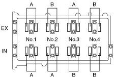
Standard valve clearance [Engine cold]
-
IN: 0.22—0.28 mm {0.009—0.011 in}EX: 0.27—0.33 mm {0.011—0.012 in}
VALVE CLEARANCE INSPECTION [MZR 2.0 DISI i-stop]
id011037803400
1. Remove the battery cover. (See BATTERY REMOVAL/INSTALLATION [MZR 2.0 DISI i-stop].)
2. Disconnect the negative battery cable.
3. Remove the plug hole plate. (See PLUG HOLE PLATE REMOVAL/INSTALLATION [MZR 2.0 DISI i-stop].)
4. Disconnect the wiring harness.
5. Remove the ignition coils. (See IGNITION COIL REMOVAL/INSTALLATION [MZR 2.0 DISI i-stop].)
6. Remove the spark plugs. (See SPARK PLUG REMOVAL/INSTALLATION [MZR 2.0 DISI i-stop].)
7. Remove the ventilation hose.
8. Remove the dipstick.
9. Remove the cylinder head cover. (See TIMING CHAIN REMOVAL/INSTALLATION [MZR 2.0 DISI i-stop].)
10. Remove the aerodynamic under cover No.2 and splash shield as a single unit. (See AERODYNAMIC UNDER COVER NO.2 REMOVAL/INSTALLATION.) (See SPLASH SHIELD REMOVAL/INSTALLATION.)
11. Measure the valve clearance.
acxuuw00000156
|
12. Install in the reverse order of removal.