|
am3zzw00005911
CLUTCH UNIT REMOVAL/INSTALLATION [J65M-R]
id0510008003m3
1. Remove the battery cover. (See BATTERY REMOVAL/INSTALLATION [MZ-CD 1.6 (Y6)].)
2. Disconnect the negative battery cable. (See BATTERY REMOVAL/INSTALLATION [MZ-CD 1.6 (Y6)].)
3. Remove the following parts:
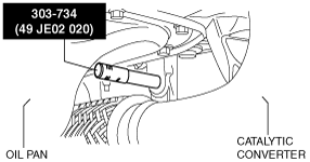
4. Cut off the vacuum chamber installation bolt and set the vacuum chamber aside so that it does not interfere with the servicing.
am3zzw00005911
|
5. Remove the starter.
6. Drain the transaxle oil into a suitable container. (See TRANSAXLE OIL REPLACEMENT [J65M-R].)
7. Remove the manual transaxle. (See MANUAL TRANSAXLE REMOVAL/INSTALLATION [J65M-R].)
8. Remove in the order indicated in the table.
9. Install in the reverse order of removal.
10. Add the specified amount of specified transaxle oil. (See TRANSAXLE OIL REPLACEMENT [J65M-R].)
11. Perform the clutch fluid line air bleeding. (See CLUTCH FLUID AIR BLEEDING/REPLACEMENT.)
am3zzw00005478
|
|
1
|
Clutch release cylinder component
|
|
2
|
Clutch cover
|
|
3
|
Clutch disc
|
|
4
|
Flywheel
(See Flywheel Removal Note.)
(See Flywheel Installation Note.)
(See FLYWHEEL INSPECTION [J65M-R].)
|
Clutch Cover and Disc Removal Note
1. Lock the flywheel using the SST.
am3zzw00007321
|
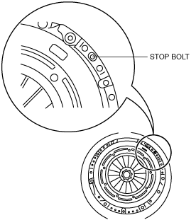
2. Unscrew the stop to loosen.
am3zzw00005479
|
3. Loosen the clutch cover installation bolts opposite each other in increments (approx. 5 passes).
am3zzw00007322
|
am3zzw00005481
|
4. Remove the clutch cover and disc.
Flywheel Removal Note
1. Lock the flywheel using the SST.
am3zzw00007321
|
2. Remove the bolts evenly and gradually in a crisscross pattern.
am3zzw00007323
|
3. Remove the flywheel.
4. Inspect for oil leakage from the crankshaft rear oil seal.
Flywheel Installation Note
1. Clean the crankshaft thread holes before installing the new flywheel installation bolts.
2. Install the flywheel to the crankshaft.
3. Hand‐tighten the new flywheel installation bolts.
4. Lock the flywheel using the SST.
am3zzw00007321
|
5. Gradually tighten the flywheel installation bolts in a crisscross pattern.
am3zzw00007324
|
Clutch Cover and Disc Installation Note
1. Lock the flywheel using the SST.
am3zzw00007321
|
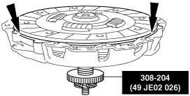
2. Using the SST, center the clutch disc on the clutch cover.
am3zzw00005484
|
3. Install the clutch cover and clutch disc to the flywheel with the SST installed.
am3zzw00007325
|
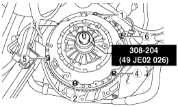
4. Tighten the new clutch cover installation bolts finger tight and then by two turns at a time in the sequence shown to the specified torque.
am3zzw00007326
|
5. Remove the SSTs.