|
1
|
INSPECT CENTER ROOF ANTENNA CONNECTOR AND TERMINALS
• Switch the ignition to off.
• Disconnect the negative battery cable.
• Disconnect the center roof antenna connector.
• Inspect the connector and terminals (corrosion, damage, pin disconnection).
• Is there any malfunction?
|
Yes
|
Repair or replace the connector or terminals, then go to Step 6.
|
|
No
|
Go to the next step.
|
|
2
|
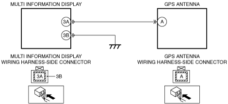
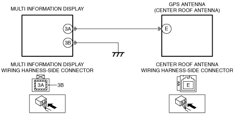
INSPECT GPS ANTENNA GROUND CIRCUIT FOR OPEN CIRCUIT
• Center roof antenna connector is disconnected.
• Inspect for continuity between the following terminals (wiring harness-side) and body ground:
-
― Multi information display terminal 3B
• Is there continuity?
|
Yes
|
Go to the next step.
|
|
No
|
Repair or replace the wiring harness for a possible open circuit, then go to Step 6.
|
|
3
|
INSPECT MULTI INFORMATION DISPLAY CONNECTOR AND TERMINALS
• Disconnect the multi information display connector.
• Inspect the connector and terminals (corrosion, damage, pin disconnection).
• Is there any malfunction?
|
Yes
|
Repair or replace the connector or terminals, then go to Step 6.
|
|
No
|
Go to the next step.
|
|
4
|
INSPECT GPS ANTENNA SIGNAL CIRCUIT FOR OPEN CIRCUIT
• Center roof antenna and multi information display connectors are disconnected.
• Inspect for continuity between the following terminals (wiring harness-side):
-
― Multi information display terminal 3A—Center roof antenna terminal E
• Is there continuity?
|
Yes
|
Go to the next step.
|
|
No
|
Repair or replace the wiring harness for a possible open circuit, then go to Step 6.
|
|
5
|
VERIFY GPS ANTENNA MALFUNCTION
• Inspect the GPS antenna.
• Is there any malfunction?
|
Yes
|
Replace the center roof antenna, then go to the next step.
|
|
No
|
Go to the next step.
|
|
6
|
VERIFY TROUBLESHOOTING COMPLETED
• Make sure to reconnect the disconnected connectors.
• Reconnect the negative battery cable.
• Clear the DTC from multi information display using the M-MDS.
• Switch the ignition to ACC.
• Perform the “DTC INSPECTION”.
• Is the same DTC present?
|
Yes
|
Replace the multi information display, then go to the next step.
|
|
No
|
Go to the next step.
|
|
7
|
VERIFY THAT NO OTHER DTCs ARE PRESENT
• Are any DTCs present?
|
Yes
|
Go to the applicable DTC inspection.
|
|
No
|
DTC troubleshooting completed.
|