ANTENNA FEEDER NO.6 INSPECTION
id092000888300
4SD
1. Disconnect the negative battery cable.
2. Remove the following parts:
- (1) Sunroof seaming welt (vehicles with sunroof)
- (2) A-pillar trim (See A-PILLAR TRIM REMOVAL/INSTALLATION.)
- (3) Front scuff plate (See FRONT SCUFF PLATE REMOVAL/INSTALLATION.)
- (4) Rear scuff plate (See REAR SCUFF PLATE REMOVAL/INSTALLATION.)
- (5) B-pillar lower trim (See B-PILLAR LOWER TRIM REMOVAL/INSTALLATION.)
- (6) Upper anchor of the front seat belt (See FRONT SEAT BELT REMOVAL/INSTALLATION.)
- (7) B-pillar upper trim (See B-PILLAR UPPER TRIM REMOVAL/INSTALLATION.)
- (8) Rear seat cushion (See REAR SEAT CUSHION REMOVAL/INSTALLATION.)
- (9) Tire house trim (See TIRE HOUSE TRIM REMOVAL/INSTALLATION.)
- (10) C-pillar trim (See C-PILLAR TRIM REMOVAL/INSTALLATION.)
- (11) Rear package trim (See REAR PACKAGE TRIM REMOVAL/INSTALLATION.)
- (12) Map light (See MAP LIGHT REMOVAL/INSTALLATION.)
- (13) Sunvisor (See SUNVISOR REMOVAL/INSTALLATION.)
- (14) Assist handle (See ASSIST HANDLE REMOVAL/INSTALLATION.)
- (15) Headliner (See HEADLINER REMOVAL/INSTALLATION.)
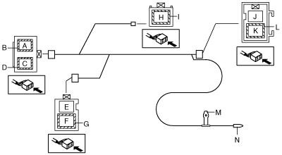
3. Disconnect the antenna feeder No.5 and connector. (See ANTENNA FEEDER NO.6 REMOVAL/INSTALLATION.)
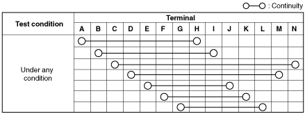
4. Verify that the continuity between antenna feeder No.6 terminals is as indicated in the table.
-
• If not as indicated in the table, replace antenna feeder No.6.
5HB
1. Disconnect the negative battery cable.
2. Remove the following parts:
- (1) Sunroof seaming welt (vehicles with sunroof)
- (2) A-pillar trim (See A-PILLAR TRIM REMOVAL/INSTALLATION.)
- (3) Front scuff plate (See FRONT SCUFF PLATE REMOVAL/INSTALLATION.)
- (4) Rear scuff plate (See REAR SCUFF PLATE REMOVAL/INSTALLATION.)
- (5) B-pillar lower trim (See B-PILLAR LOWER TRIM REMOVAL/INSTALLATION.)
- (6) Upper anchor of the front seat belt (See FRONT SEAT BELT REMOVAL/INSTALLATION.)
- (7) B-pillar upper trim (See B-PILLAR UPPER TRIM REMOVAL/INSTALLATION.)
- (8) Rear seat cushion (See REAR SEAT CUSHION REMOVAL/INSTALLATION.)
- (9) Tire house trim (See TIRE HOUSE TRIM REMOVAL/INSTALLATION.)
- (10) Trunk side upper trim (See TRUNK SIDE UPPER TRIM REMOVAL/INSTALLATION.)
- (11) C-pillar trim (See C-PILLAR TRIM REMOVAL/INSTALLATION.)
- (12) Map light (See MAP LIGHT REMOVAL/INSTALLATION.)
- (13) Sunvisor (See SUNVISOR REMOVAL/INSTALLATION.)
- (14) Assist handle (See ASSIST HANDLE REMOVAL/INSTALLATION.)
- (15) Headliner (See HEADLINER REMOVAL/INSTALLATION.)
- (16) Liftgate upper trim (with RDS (radio data system)) (See LIFTGATE UPPER TRIM REMOVAL/INSTALLATION.)
3. Disconnect the antenna feeder No.5 and connector. (See ANTENNA FEEDER NO.6 REMOVAL/INSTALLATION.)
4. Disconnect the antenna feeder No.7. (See ANTENNA FEEDER NO.7 REMOVAL/INSTALLATION.)
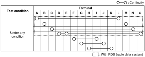
5. Verify that the continuity between antenna feeder No.6 terminals is as indicated in the table.
-
• If not as indicated in the table, replace antenna feeder No.6.