DTC B1317, B1318 [DYNAMIC STABILITY CONTROL (DSC)]


id0402b2800300

DTC
B1317, B1318
Power supply system
DETECTION CONDITION
•  B1317
―  High ignition voltage (16 V or more) is detected at the voltage monitor of the solenoid valve or motor monitor.
•  B1318
―  When driving the vehicle at 20 km/h {12.4 mph} or more, low ignition voltage (10 V or less) is detected at the voltage monitor of the solenoid valve or motor monitor.
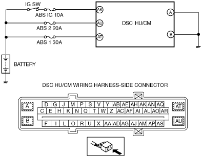
POSSIBLE CAUSE
•  ABS 1 30A/ABS 2 20A/ABS IG 10A fuse malfunction
•  Open or short circuit in the wiring harness between DSC HU/CM terminal AK and battery
•  Open or short circuit in the wiring harness between DSC HU/CM terminal AU and battery
•  Open or short circuit in the wiring harness between DSC HU/CM terminal AT and battery
•  Open circuit in the wiring harness between DSC HU/CM terminal A and body ground
•  Open circuit in the wiring harness between DSC HU/CM terminal B and body ground
•  Battery deterioration
•  Generator malfunction
•  Poor connection at connectors (female terminal)

Diagnostic procedure

STEP

INSPECTION

ACTION

1
INSPECT BATTERY VOLTAGE
•  Is the battery terminal voltage normal?
Yes
Verify that the battery terminal connection is normal.
Go to the next step.
No
Recharge or replace the battery, then go to Step 6.
2
INSPECT BATTERY GRAVITY
•  Is the battery specific gravity as specified?
Yes
Go to the next step.
No
Replace the battery, then go to Step 6.
3
INSPECT CHARGING SYSTEM
•  Are the generator and the drive belt tensions normal?
Yes
Go to the next step.
No
Replace the generator and/or drive belt if necessary.
Go to Step 6.
4
INSPECT DSC HU/CM POWER SUPPLY FOR OPEN CIRCUIT
•  Disconnect the DSC HU/CM connectors.
•  Turn the ignition switch to the ON position.
•  Measure the voltage between following connector terminals of the DSC HU/CM (vehicle harness-side) and body ground:
―  DSC HU/CM: AK—Body ground
―  DSC HU/CM: AU—Body ground
―  DSC HU/CM: AT—Body ground
•  Is the voltage 10 V or more?
Yes
Go to the next step.
No
Repair or replace the wiring harness, then go to Step 6.
5
INSPECT DSC HU/CM GROUND FOR POOR GROUND OR OPEN CIRCUIT
•  Turn the ignition switch off.
•  Measure the resistance between following connector terminals of the DSC HU/CM (vehicle harness-side) and body ground:
―  DSC HU/CM: A—Body ground
―  DSC HU/CM: B—Body ground
•  Is the resistance within 0—1 ohm?
Yes
Go to the next step.
No
If there is open circuit:
•  Repair or replace the wiring harness, then go to the next step.
If resistance is not within specification:
•  Repair or replace the wiring harness for poor ground, then go to the next step.
6
VERIFY THAT THE SAME DTC IS NOT PRESENT
•  Reconnect all disconnected connectors.
•  Clear the DTCs from the memory.
•  Start the engine and drive the vehicle at 20 km/h {12.4 mph} or more.
•  Are the same DTCs present?
Yes
Repeat the inspection from Step 1.
No
Go to the next step.
7
VERIFY THAT NO OTHER DTCS ARE PRESENT
•  Are any other DTCs output?
Yes
Go to the applicable DTC inspection.
No
DTC troubleshooting completed.