|
am6zzw00004343
OIL PUMP REMOVAL/INSTALLATION [MZR-CD 2.2]
id0111f2800600
1. Complete the “BEFORE SERVICE PRECAUTION”. (See BEFORE SERVICE PRECAUTION [MZR-CD 2.2].)
2. Drain the engine oil. (See ENGINE OIL REPLACEMENT [MZR-CD 2.2].)
3. Disconnect the negative battery cable. (See BATTERY REMOVAL/INSTALLATION [MZR-CD 2.2].)
4. Remove the engine cover. (See ENGINE COVER REMOVAL/INSTALLATION [MZR-CD 2.2].)
5. Disconnect the ventilation hose.
6. Disconnect the following parts and set the fuel injector wiring harness out of the way.
am6zzw00004343
|
7. Remove the fuel injectors. (See FUEL INJECTOR REMOVAL/INSTALLATION [MZR-CD 2.2].)
8. Remove the camshaft position sensor. (See CAMSHAFT POSITION (CMP) SENSOR REMOVAL/INSTALLATION [MZR-CD 2.2].)
9. Remove the front wheel and tire. (RH) (See GENERAL PROCEDURES (SUSPENSION).)
10. Remove the aerodynamic under cover No.2 and splash shield as a single unit. (See AERODYNAMIC UNDER COVER NO.2 REMOVAL/INSTALLATION.) (See SPLASH SHIELD REMOVAL/INSTALLATION.)
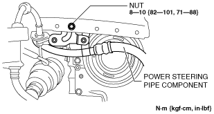
11. Remove the nut shown in the figure and set the power steering pipe component out of the way.
am3zzw00007021
|
12. Remove the drive belt. (See DRIVE BELT REMOVAL/INSTALLATION [MZR-CD 2.2].)
13. Remove the crankshaft position sensor. (See CRANKSHAFT POSITION (CKP) SENSOR REMOVAL/INSTALLATION [MZR-CD 2.2].)
14. Remove the fuel filter component with the hose still connected and set it out of the way. (L.H.D.) (See FUEL FILTER REMOVAL/INSTALLATION [MZR-CD 2.2].)
15. Remove the coolant reserve tank with the hose still connected and set it out of the way. (See COOLANT RESERVE TANK REMOVAL/INSTALLATION [MZR-CD 2.2].)
16. Remove the engine front cover. (See TIMING CHAIN REMOVAL/INSTALLATION [MZR-CD 2.2].)
17. Remove the oil pan. (See OIL PAN REMOVAL/INSTALLATION [MZR-CD 2.2].)
18. Remove in the order indicated in the table.
19. Install in the reverse order of removal.
20. Complete the “AFTER SERVICE PRECAUTION’’. (See AFTER SERVICE PRECAUTION [MZR-CD 2.2].)
21. Start the engine and confirm that there is no oil leakage.
22. Inspect the oil level.
23. Inspect for the idle speed. (See ENGINE TUNE-UP [MZR-CD 2.2].)
24. Inspect the oil pressure. (See OIL PRESSURE INSPECTION [MZR-CD 2.2].)
am6zzw00007294
|
|
1
|
Balancer chain tensioner
|
|
2
|
Balancer chain tensioner arm
|
|
3
|
Balancer sprocket
|
|
4
|
Balancer component
|
|
5
|
Oil pump
(See Oil Pump Installation Note.)
|
Balancer Chain Tensioner Removal Note
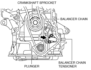
1. Press back the plunger for the balancer chain tensioner slowly in the direction shown in the figure.
am6zzw00007028
|
2. While holding the balancer chain tensioner plunger, insert the hexagonal wrench into the position shown in the figure and secure the plunger.
am6zzw00007029
|
3. Remove the balancer chain tensioner.
Balancer Sprocket Removal Note
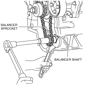
1. Hold the balancer shaft using a wrench on the cast hexagon and loosen the balancer sprocket lock bolt.
am6zzw00007030
|
2. Remove the balancer sprocket.
Oil Pump Installation Note
1. Tighten the oil pump installation bolts in the order shown in the figure.
am6zzw00007295
|
Balancer Sprocket Installation Note
am3zzw00006916
|
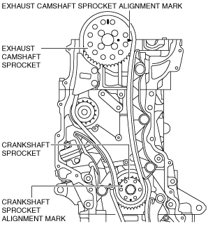
1. Rotate the crankshaft until the exhaust camshaft and the crankshaft sprocket alignment marks are in the positions shown in the figure. (No.2 piston is at TDC.)
am3zzw00010884
|
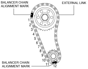
2. Set the balancer chain to the balancer chain drive gear so that the balancer chain alignment mark (gold colored link) aligns with the balancer chain drive gear alignment mark.
am6zzw00007032
|
3. Install the balancer sprocket to the balancer chain so that the balancer sprocket alignment mark aligns with the balancer chain alignment mark (gold colored link).
4. Install the balancer sprocket to the balancer unit and temporarily install the balancer sprocket lock bolt.
5. Secure the balancer shaft using a wrench on the cast hexagon.
am6zzw00007033
|
6. Tighten the balancer sprocket lock bolt.
Balancer Chain Tensioner Installation Note
1. Install the balancer chain tensioner.
2. Remove the hexagonal wrench which has been installed to secure the plunger.