 |
am3zzw00007905
STARTER REMOVAL/INSTALLATION [MZR 2.0 DISI i-stop]
id011937800200
Operation After Replacing Starter
|
STEP |
ACTION |
NOTE |
|---|---|---|
|
1
|
Replace the starter.
|
|
|
2
|
Reset the number of times the starter can operate using the M-MDS.
Verify the i-stop warning light (amber).
• If it flashes, go to the next step.
• If it does not flash, go to Step 4.
|
|
|
3
|
Clear applicable DTCs using the M-MDS.
|
|
|
4
|
Close the bonnet.
|
• Because the sub battery recharge is not available while the bonnet is open, the procedure is not completed.
|
|
5
|
Warm up the engine. (no electrical load)
|
|
|
6
|
Switch the ignition off.
|
|
|
7
|
Long-press the i-stop OFF switch for 3 s within 5 s after switching the ignition ON.
|
|
|
8
|
Start the engine.
|
|
|
9
|
Press the i-stop OFF switch.
Verify that the i-stop indicator light (green) flashes.
• If it does not flash, go back to Step 7.
|
|
|
10
|
Maintain the idle status (no electrical load) until the i-stop indicator light (green) turns off.
|
• For operating i-stop, learning is required for the following two items:
Initial learning/recharging for battery charge condition
ISC learning
• If the above two operations are successfully completed, the i-stop indicator light (green) turns off.
|
|
11
|
Verify that the engine stops via the i-stop control and then restarts.
• If it cannot be verified, inspect the i-stop system-related units for DTCs.
|
|
|
12
|
Switch the ignition off, and start the engine.
|
• The display function for the i-stop indicator light (green) is reset.
|
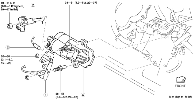
Starter Removal/Installation
1. Remove the battery cover. (See BATTERY REMOVAL/INSTALLATION [MZR 2.0 DISI i-stop].)
2. Disconnect the negative battery cable. (See BATTERY REMOVAL/INSTALLATION [MZR 2.0 DISI i-stop].)
3. Remove the aerodynamic under cover No.2. (See AERODYNAMIC UNDER COVER NO.2 REMOVAL/INSTALLATION.)
4. Remove in the order indicated in the table.
5. Install in the reverse order of removal.
am3zzw00007905
|
|
1
|
Wiring harness bracket
|
|
2
|
Terminal B cable
|
|
3
|
Terminal S connector
|
|
4
|
Starter
(See Starter removal note.)
(See Starter installation note.)
|
Starter removal note
1. Remove the starter from the underside of the vehicle.
Starter installation note
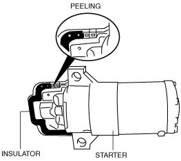
am6zzw00002371
|
1. Peel off the insulator from the starter completely using a scraper.
2. Degrease the insulator attachment area.
am6zzw00002372
|
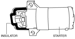
3. Attach a new insulator to the starter.
am6zzw00002373
|