 |
am3uuw00006336
JOINT SHAFT REMOVAL/INSTALLATION [MZR 1.5, MZR 1.6, MZR 2.3 DISI Turbo, MZR 2.5]
id0313008009l1
1. Remove the aerodynamic under cover No.2 and splash shield as a unit. (See AERODYNAMIC UNDER COVER NO.2 REMOVAL/INSTALLATION.) (See SPLASH SHIELD REMOVAL/INSTALLATION.)
2. Drain the transaxle oil or ATF. (See TRANSAXLE OIL REPLACEMENT [F35M-R].) (See TRANSAXLE OIL REPLACEMENT [G66M-R].) (See TRANSAXLE OIL REPLACEMENT [A26M-R].) (See CVT (CONTINUOUSLY VARIABLE TRANSAXLE) FLUID REPLACEMENT [DJVA-EL].) (See AUTOMATIC TRANSAXLE FLUID (ATF) REPLACEMENT [FN4A-EL].) (See AUTOMATIC TRANSAXLE FLUID (ATF) REPLACEMENT [FS5A-EL].)
3. Remove the WU-TWC bracket. (MZR 2.3 DISI Turbo) (See EXHAUST SYSTEM REMOVAL/INSTALLATION [MZR 2.3 DISI Turbo].)
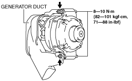
4. Remove the generator duct fitting nuts, and position it in the engine compartment in a location where no part can be damaged as shown in the figure. (MZR 2.3 DISI Turbo)
am3uuw00006336
|
5. Remove in the order indicated in the table.
6. Install in the reverse order of removal.
am3zzw00011421
|
|
1
|
ABS wheel-speed sensor connector
|
|
2
|
Tie-rod end ball joint
|
|
3
|
Stabilizer control link upper nut
|
|
4
|
Dynamic damper
|
|
5
|
Front lower arm ball joint
|
|
6
|
Joint shaft
(See Joint Shaft Removal Note.)
|
|
7
|
Joint shaft clip
|
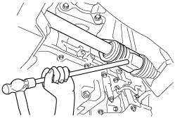
Joint Shaft Removal Note
1. Disconnect the drive shaft (RH) from the joint shaft by tapping the transaxle side outer ring with a brass bar and hammer.
am3zzw00002051
|
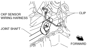
2. Disconnect the clips to set the CKP sensor harness out of the way to prevent interference with the joint shaft. (MZR 2.5)
am3uuw00004598
|
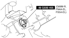
3. Disconnect the joint shaft bracket from the cylinder block and remove the joint shaft.
4. Install the SST to the transaxle after the joint shaft is removed.
am3zzw00013212
|
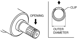
Joint Shaft Clip Installation Note
1. Install a new joint shaft clip to the clip groove at the end of the joint shaft with the clip opening facing upward and the clip width within the specification.
2. After installation, measure the outer diameter.
am3uuw00006183
|
Joint Shaft Installation Note
1. Insert the joint shaft into the transaxle.
2. Temporarily tighten the bolts A and B.
am3zzw00011422
|
3. Tighten the bolts A, then tighten the bolt B to the specified torque.
Front Lower Arm Ball Joint Installation Note