CLUTCH UNIT REMOVAL/INSTALLATION [B76M-R]
id0510001572m9
-
Caution
-
• Do not allow clutch fluid get on a painted surface. Clutch fluid contains properties which can dissolve the paint. If clutch fluid gets on a painted surface, wash it off with water immediately and wipe the area off completely.
1. Disconnect the negative battery cable.
2. Remove the aerodynamic under cover No.2 and the splash shield as a single unit. (See AERODYNAMIC UNDER COVER NO.2 REMOVAL/INSTALLATION.) (See SPLASH SHIELD REMOVAL/INSTALLATION.)
3. Drain the manual transaxle oil. (See MANUAL TRANSAXLE OIL REPLACEMENT [B76M-R].)
4. Disconnect and/or remove the following parts in the engine compartment.
- (1) Remove the air cleaner component. (ex: air cleaner, air hose) (See INTAKE-AIR SYSTEM REMOVAL/INSTALLATION [MZ-CD 1.6].)
- (2) Remove the battery component. (ex: battery, battery tray) (See BATTERY REMOVAL/INSTALLATION [MZ-CD 1.6].)
- (3) Disconnect the clutch pipe and hose No.2 from MTX and the clutch release cylinder, and plug it to avoid clutch fluid leakage. (See CLUTCH PIPE AND HOSE REMOVAL/INSTALLATION [B76M-R].)
- (4) Disconnect the control cable from MTX. (See MANUAL TRANSAXLE SHIFT MECHANISM REMOVAL/INSTALLATION.)
- (5) Disconnect the connectors and GND wiring harness from the MTX.
- (6) Remove the brackets from MTX.
- (7) Remove the catalyst converter front insulator installation bolts and set the exhaust manifold insulator aside. (SeeEXHAUST SYSTEM REMOVAL/INSTALLATION [MZ-CD 1.6].)
5. Disconnect and/or remove the following parts related to the suspension and axle.
- (1) Remove the front tires. (See GENERAL PROCEDURES (FRONT AND REAR AXLES).)
- (2) Disconnect the clip securing the brake hose from the shock absorber. (See BRAKE HOSE (FRONT) REMOVAL/INSTALLATION [EXCEPT MZR 2.3 DISI Turbo].)
- (3) Disconnect the ABS wheel-speed sensors from the steering knuckles. (See FRONT ABS WHEEL-SPEED SENSOR REMOVAL/INSTALLATION.)
- (4) Disconnect the tie-rod end ball joints from the steering knuckles. (See FRONT CROSSMEMBER REMOVAL/INSTALLATION [MZR 1.5, MZR 1.6, MZR 2.0, MZR 2.3 DISI Turbo, MZR 2.5, MZ-CD 1.6].)
- (5) Disconnect the stabilizer control links (upper side) from the shock absorbers. (See FRONT STABILIZER REMOVAL/INSTALLATION [EXCEPT MZR 2.3 DISI Turbo].)
- (6) Disconnect the front lower arms from the steering knuckles. (See FRONT CROSSMEMBER REMOVAL/INSTALLATION [MZR 1.5, MZR 1.6, MZR 2.0, MZR 2.3 DISI Turbo, MZR 2.5, MZ-CD 1.6].)
- (7) Disconnect the drive shaft (LH) from the MTX. (See DRIVE SHAFT REMOVAL/INSTALLATION.)
- (8) Disconnect the drive shaft (RH) from the joint shaft. (See DRIVE SHAFT REMOVAL/INSTALLATION.)
- (9) Remove the joint shaft. (See JOINT SHAFT REMOVAL/INSTALLATION [MZ-CD 1.6, MZR-CD 2.2].)
6. Disconnect and/or remove the following parts from the underside of the vehicle.
- (1) Remove the hanger rubber as shown in the figure.
-
- (2) Remove the starter. (See STARTER REMOVAL/INSTALLATION [MZ-CD 1.6].)
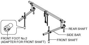
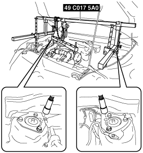
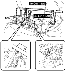
7. Install the SST using the following procedure.
-
Caution
-
• Refer to the SST instruction manual for the basic handing procedure.
- (1) Align the bolt of the shock absorber (RH) shown in the figure with the rear shaft hole for the right side of the SST.
-
- (2) Align the bolt of the shock absorber (LH) shown in the figure with the rear shaft hole for the left side of the SST.
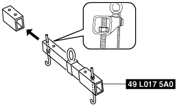
- (3) Install one front foot No.2 to each of the left and right front shafts of the SST, and then align the holes of the SST front shafts with the bolt on the left and right side of each front side frame.
-
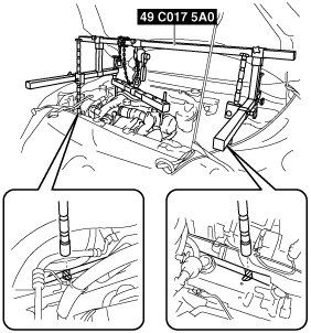
- (4) Set the SST as shown in the figure.
-
- (5) Set the SST as shown in the figure.
-
- (6) Adjust the height of the left and right side bars so that they are leveled, then tighten each part of the SST.
- (7) Make sure each joint is securely tightened.
8. Remove the MTX. (See MANUAL TRANSAXLE REMOVAL/INSTALLATION [B76M-R].)
9. Remove in the order indicated in the table.
10. Install in the reverse order of removal.
11. Add the specified amount of specified transaxle oil. (See MANUAL TRANSAXLE OIL REPLACEMENT [B76M-R].)
12. Bleed the air from the clutch system. (See CLUTCH FLUID REPLACEMENT/AIR BLEEDING [B76M-R].)
|
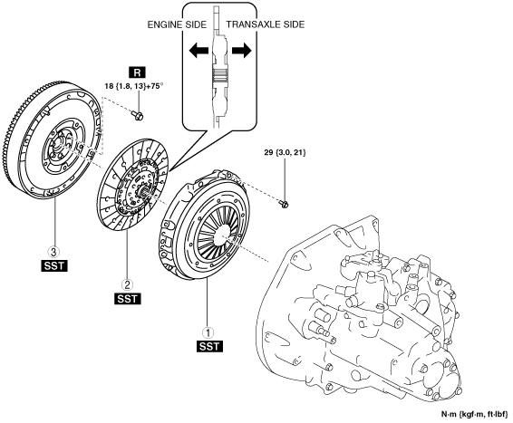
1
|
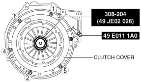
Clutch cover
|
|
2
|
Clutch disc
|
|
3
|
Flywheel
|
Clutch Cover and Disc Removal Note
1. Hold the clutch unit using the SST.
2. Loosen each bolt one turn at a time in a crisscross pattern until spring tension is released.
3. Remove the clutch cover and disc.
Flywheel Removal Note
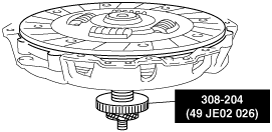
1. Hold the flywheel using the SST.
2. Remove the lock bolts, and remove the flywheel.
3. Inspect for oil leakage from the crankshaft rear oil seal.
-
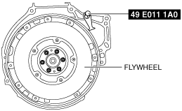
Flywheel Installation Note
1. Clean the crankshaft thread holes.
2. Install the flywheel to the crankshaft.
3. Temporarily tighten the new lock bolts.
4. Hold the flywheel using the SST.
5. Tighten the lock bolts in the order shown in the figure to the specified angle and install the flywheel.
-
Tightening torque
-
18 N·m {1.8 kgf·m, 13 ft·lbf}+75°
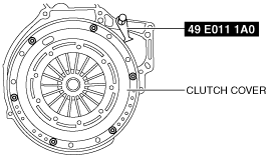
Clutch Disc and Cover Installation Note
1. Assemble the clutch cover and disc, and install the SST as shown in the figure.
2. Install the clutch cover and disc to the flywheel with the SSTs installed.
3. Tighten the bolts evenly and gradually in the order shown in the figure.
-
Tightening torque
-
29 N·m {3.0 kgf·m, 21 ft·lbf}
4. Remove the SSTs.