 |
am3zzw00007413
AUTOMATIC TRANSAXLE SHIFT MECHANISM REMOVAL/INSTALLATION
id051800296900
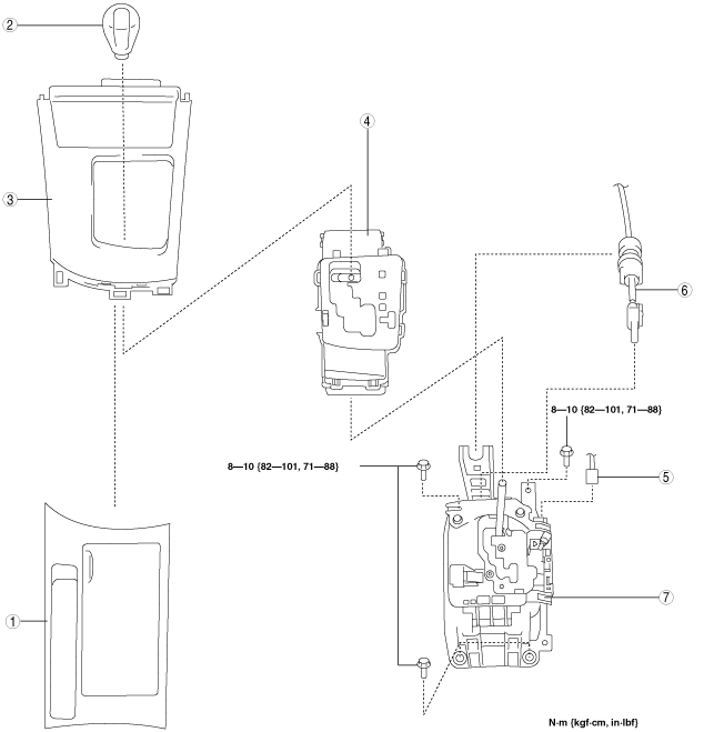
Selector Lever Removal/Installation
1. Remove the battery cover. (See BATTERY REMOVAL/INSTALLATION [MZR 1.5, MZR 1.6].) (See BATTERY REMOVAL/INSTALLATION [MZR 2.0, MZR 2.5].) (See BATTERY REMOVAL/INSTALLATION [SKYACTIV-G 2.0].)
2. Disconnect the negative battery cable. (See BATTERY REMOVAL/INSTALLATION [MZR 1.5, MZR 1.6].) (See BATTERY REMOVAL/INSTALLATION [MZR 2.0, MZR 2.5].) (See BATTERY REMOVAL/INSTALLATION [SKYACTIV-G 2.0].)
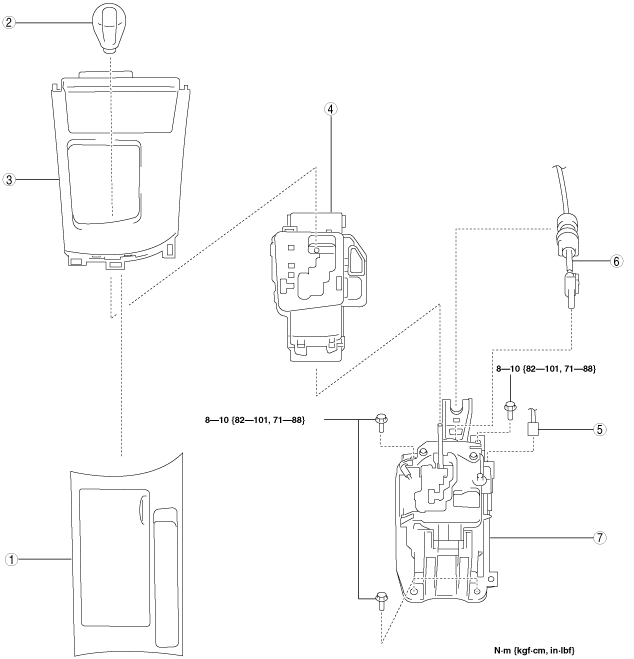
3. Remove in the order indicated in the table.
4. Install in the reverse order of removal.
L.H.D.
am3zzw00007413
|
|
1
|
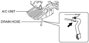
Upper panel
|
|
2
|
Knob
|
|
3
|
Shift panel
|
|
4
|
Indicator panel
|
|
5
|
Connector
|
|
6
|
Selector cable (selector lever side)
|
|
7
|
Selector lever
|
R.H.D.
am3zzw00005089
|
|
1
|
Upper panel
|
|
2
|
Knob
|
|
3
|
Shift panel
|
|
4
|
Indicator panel
|
|
5
|
Connector
|
|
6
|
Selector cable (selector lever side)
|
|
7
|
Selector lever
|
Shift panel and indicator panel removal note
1. Remove the shift panel and indicator panel as a single unit.
L.H.D.
am3uuw00003049
|
R.H.D.
am3zzw00005057
|
L.H.D.
am3zzw00007414
|
R.H.D.
am3zzw00005058
|
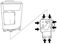
2. Detach the hooks as shown in the figure and remove the indicator panel from the shift panel.
L.H.D.
am3zzw00007415
|
R.H.D.
am3zzw00005059
|
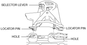
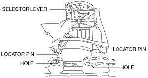
Selector lever installation note
1. Align the locator pin with the hole in the floor as shown in the figure and install the selector lever.
L.H.D.
am3uuw00003052
|
R.H.D.
am3zzw00005103
|
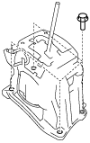
2. Tighten the selector lever installation bolts.
L.H.D.
am3uuw00003053
|
R.H.D.
am3zzw00005060
|
Selector cable (selector lever side) installation note
1. Install the selector cable end (selector lever side) as shown in the figure.
L.H.D.
am3uuw00003067
|
R.H.D.
am3zzw00005061
|
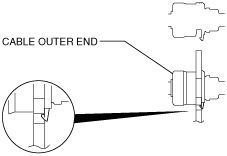
2. Install the cable outer end (selector lever side) to the selector cable bracket as shown in the figure.
am3uuw00003062
|
3. Adjust the selector cable. (See Selector Cable Adjustment.)
Indicator panel and shift panel installation note
1. Install the shift panel to the indicator panel.
L.H.D.
am3zzw00007416
|
R.H.D.
am3zzw00005062
|
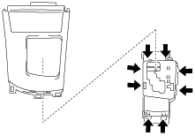
2. Install the shift panel and indicator panel to the selector lever as a single unit.
L.H.D.
am3zzw00007417
|
R.H.D.
am3zzw00005058
|
3. Connect the bulb socket to the indicator panel.
L.H.D.
am3uuw00003056
|
R.H.D.
am3zzw00005063
|
4. Install the shift panel and indicator panel to the console and ashtray panel as a single unit. (See SHIFT PANEL REMOVAL/INSTALLATION)
Selector Cable Removal/Installation
1. Remove the battery cover. (See BATTERY REMOVAL/INSTALLATION [MZR 1.5, MZR 1.6].) (See BATTERY REMOVAL/INSTALLATION [MZR 2.0, MZR 2.5].) (See BATTERY REMOVAL/INSTALLATION [SKYACTIV-G 2.0].)
2. Disconnect the negative battery cable. (See BATTERY REMOVAL/INSTALLATION [MZR 1.5, MZR 1.6].) (See BATTERY REMOVAL/INSTALLATION [MZR 2.0, MZR 2.5].) (See BATTERY REMOVAL/INSTALLATION [SKYACTIV-G 2.0].)
3. Remove the battery. (See BATTERY REMOVAL/INSTALLATION [MZR 1.5, MZR 1.6].) (See BATTERY REMOVAL/INSTALLATION [MZR 2.0, MZR 2.5].) (See BATTERY REMOVAL/INSTALLATION [SKYACTIV-G 2.0].)
4. Remove the battery box. (See BATTERY REMOVAL/INSTALLATION [MZR 1.5, MZR 1.6].) (See BATTERY REMOVAL/INSTALLATION [MZR 2.0, MZR 2.5].) (See BATTERY REMOVAL/INSTALLATION [SKYACTIV-G 2.0].)
5. Remove the battery tray. (See BATTERY REMOVAL/INSTALLATION [MZR 1.5, MZR 1.6].) (See BATTERY REMOVAL/INSTALLATION [MZR 2.0, MZR 2.5].) (See BATTERY REMOVAL/INSTALLATION [SKYACTIV-G 2.0].)
6. Remove the air cleaner component. (MZR 2.0, SKYACTIV-G 2.0, MZR 2.5) (See INTAKE-AIR SYSTEM REMOVAL/INSTALLATION [MZR 2.0, MZR 2.5].) (See INTAKE-AIR SYSTEM REMOVAL/INSTALLATION [SKYACTIV-G 2.0].)
7. Remove the aerodynamic under cover No.2. (See AERODYNAMIC UNDER COVER NO.2 REMOVAL/INSTALLATION.)
8. Remove the tunnel member (rear). (See EXHAUST SYSTEM REMOVAL/INSTALLATION [MZR 1.5, MZR 1.6].) (See EXHAUST SYSTEM REMOVAL/INSTALLATION [MZR 2.0, MZR 2.5].)
9. Remove the brace bar. (SKYACTIV-G 2.0) (See EXHAUST SYSTEM REMOVAL/INSTALLATION [SKYACTIV-G 2.0].)
10. Remove the insulator (front) installation nuts and set the insulator (front) aside. (See EXHAUST SYSTEM REMOVAL/INSTALLATION [MZR 1.5, MZR 1.6].) (See EXHAUST SYSTEM REMOVAL/INSTALLATION [MZR 2.0, MZR 2.5].) (See EXHAUST SYSTEM REMOVAL/INSTALLATION [SKYACTIV-G 2.0].)
11. Remove the upper panel. (See UPPER PANEL REMOVAL/INSTALLATION.)
12. Remove the knob. (See Selector Lever Removal/Installation .)
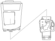
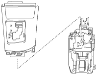
13. Remove the shift panel and indicator panel as a single unit.
L.H.D.
am3uuw00003057
|
R.H.D.
am3zzw00005064
|
L.H.D.
am3zzw00007412
|
R.H.D.
am3zzw00005058
|
14. Remove the console. (See CONSOLE REMOVAL/INSTALLATION.)
15. Disconnect the drain hose connected to A/C unit. (See A/C UNIT REMOVAL/INSTALLATION.)
am3uuw00004384
|
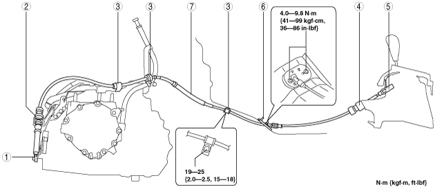
16. Remove in the order indicated in the table.
17. Install in reverse of removal.
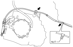
FN4A-EL
am3zzw00007410
|
|
1
|
Selector cable end (transaxle side)
|
|
2
|
Cable outer end (transaxle side)
|
|
3
|
Clip
|
|
4
|
Cable outer end (selector lever side)
|
|
5
|
Selector cable end (selector lever side)
|
|
6
|
Grommet
|
|
7
|
Selector cable
|
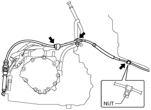
FS5A-EL
am3uuw00003059
|
|
1
|
Selector cable end (transaxle side)
|
|
2
|
Cable outer end (transaxle side)
|
|
3
|
Clip
|
|
4
|
Cable outer end (selector lever side)
|
|
5
|
Selector cable end (selector lever side)
|
|
6
|
Grommet
|
|
7
|
Selector cable
|
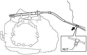
FW6A-EL
am3uuw00008344
|
|
1
|
Selector cable end (transaxle side)
|
|
2
|
Cable outer end (transaxle side)
|
|
3
|
Clip
|
|
4
|
Cable outer end (selector lever side)
|
|
5
|
Selector cable end (selector lever side)
|
|
6
|
Grommet
|
|
7
|
Selector cable
|
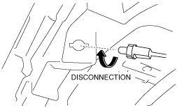
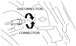
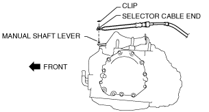
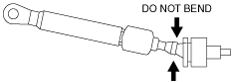
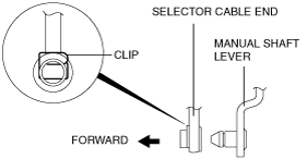
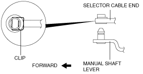
Selector cable end (transaxle side) removal note
1. Remove the clip, and then disconnect the selector cable end from the manual shaft lever.
FN4A-EL, FS5A-EL
am3uuw00003060
|
FW6A-EL
am3uuw00008345
|
Selector cable installation note
1. Install the grommet as shown in the figure.
am3uuw00003066
|
2. Install the selector cable end (selector lever side) as shown in the figure.
L.H.D.
am3uuw00003067
|
R.H.D.
am3zzw00005065
|
3. Install the cable outer end (selector lever side) to the selector cable bracket as shown in the figure.
am3uuw00003062
|
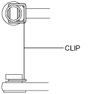
4. Install the clip as shown in the figure and tighten the nut.
FN4A-EL
am3zzw00007411
|
FS5A-EL
am3uuw00003065
|
FW6A-EL
am3uuw00008346
|
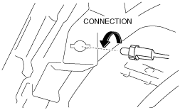
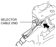
5. Install the selector cable end (transaxle side) and the cable outer end (transaxle side).
am3zzw00007418
|
am3uuw00003062
|
am3uuw00003063
|
FN4A-EL, FS5A-EL
am3uuw00003064
|
FW6A-EL
am3uuw00008347
|
6. Verify that the selector cable is securely installed.
7. Adjust the selector cable. (See Selector Cable Adjustment.)
Bulb Removal/Installation
1. Remove the battery cover. (See BATTERY REMOVAL/INSTALLATION [MZR 1.5, MZR 1.6].) (See BATTERY REMOVAL/INSTALLATION [MZR 2.0, MZR 2.5].) (See BATTERY REMOVAL/INSTALLATION [SKYACTIV-G 2.0].)
2. Disconnect the negative battery cable. (See BATTERY REMOVAL/INSTALLATION [MZR 1.5, MZR 1.6].) (See BATTERY REMOVAL/INSTALLATION [MZR 2.0, MZR 2.5].) (See BATTERY REMOVAL/INSTALLATION [SKYACTIV-G 2.0].)
3. Remove the upper panel. (See UPPER PANEL REMOVAL/INSTALLATION.)
4. Remove the knob. (See Selector Lever Removal/Installation .)
5. Remove the shift panel and indicator panel as a single unit.
L.H.D.
am3uuw00003057
|
R.H.D.
am3zzw00005064
|
L.H.D.
am3zzw00007412
|
R.H.D.
am3zzw00005058
|
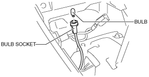
6. Remove the bulb from the bulb socket.
am3zzw00006044
|
7. Install in the reverse order of removal.
Selector Cable Adjustment
1. Remove the battery cover. (See BATTERY REMOVAL/INSTALLATION [MZR 1.5, MZR 1.6].) (See BATTERY REMOVAL/INSTALLATION [MZR 2.0, MZR 2.5].) (See BATTERY REMOVAL/INSTALLATION [SKYACTIV-G 2.0].)
2. Disconnect the negative battery cable. (See BATTERY REMOVAL/INSTALLATION [MZR 1.5, MZR 1.6].) (See BATTERY REMOVAL/INSTALLATION [MZR 2.0, MZR 2.5].) (See BATTERY REMOVAL/INSTALLATION [SKYACTIV-G 2.0].)
3. Remove the upper panel. (See UPPER PANEL REMOVAL/INSTALLATION.)
4. Remove the knob. (See Selector Lever Removal/Installation .)
5. Remove the shift panel and indicator panel as a single unit.
L.H.D.
am3uuw00003057
|
R.H.D.
am3zzw00005064
|
L.H.D.
am3zzw00007412
|
R.H.D.
am3zzw00005058
|
6. Shift the selector lever to the P position.
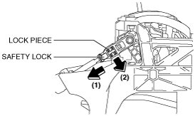
7. Unlock the lock piece of the selector cable end (selector lever side) in the order as shown in the figure.
L.H.D.
am3uuw00003072
|
R.H.D.
am3zzw00005104
|
8. Verify that the manual shaft is in the P position.
9. Lock the lock piece and safety lock of the selector cable end (selector lever side) in the order as shown in the figure.
L.H.D.
am3uuw00003073
|
R.H.D.
am3zzw00005105
|