|
1
|
CONFIRM BCM DTC
• Clear the DTC using the M-MDS.
• Perform the BCM DTC inspection using the M-MDS with the selector lever in P or N position.
• Is the same DTC present?
|
Yes
|
Go to the next step.
|
|
No
|
Go to Step 7.
|
|
2
|
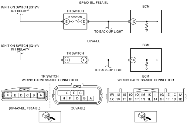
INSPECT TR SWITCH CONNECTOR AND TERMINALS
• Switch the ignition to off.
• Disconnect the negative battery cable.
• Disconnect the TR switch connector.
• Inspect the connector and terminals (corrosion, damage, pin disconnection).
• Is there any malfunction?
|
Yes
|
Repair or replace the connector or terminals, then go to Step 6.
|
|
No
|
Go to the next step.
|
|
3
|
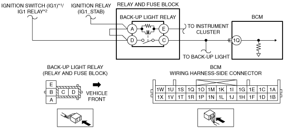
INSPECT BCM CONNECTOR AND TERMINALS
• Disconnect the BCM connector.
• Inspect the connector and terminals (corrosion, damage, pin disconnection).
• Is there any malfunction?
|
Yes
|
Repair or replace the connector or terminals, then go to Step 6.
|
|
No
|
Go to the next step.
|
|
4
|
INSPECT TR SWITCH CIRCUIT FOR SHORT TO POWER SUPPLY
• Verify that the TR switch and BCM connectors are disconnected.
• Reconnect the negative battery cable.
• Switch the ignition to ON.
• Measure the voltage at the following terminal (wiring harness-side):
-
― GF4AX-EL, FS5A-EL:
-
• TR switch terminal D
― DJVA-EL:
-
• TR switch terminal E
• Is there any voltage?
|
Yes
|
Repair or replace the wiring harness for a possible short to power supply, then go to Step 6.
|
|
No
|
Go to the next step.
|
|
5
|
INSPECT TR SWITCH
• Is there any malfunction?
|
Yes
|
Replace the TR switch, then go to the next step.
|
|
No
|
Go to the next step.
|
|
6
|
VERIFY TROUBLESHOOTING COMPLETED
• Make sure to reconnect all disconnected connectors.
• Reconnect the negative battery cable.
• Clear the DTC using the M-MDS.
• Perform the BCM DTC inspection using the M-MDS with the selector lever in P or N position.
• Is the same DTC present?
|
Yes
|
Repeat the inspection from Step 1.
• If the malfunction recurs, replace the BCM.
Go to the next step.
|
|
No
|
Go to the next step.
|
|
7
|
VERIFY THAT NO OTHER DTCs ARE PRESENT
• Are any DTCs present?
|
Yes
|
Go to the applicable DTC inspection.
|
|
No
|
DTC troubleshooting completed.
|