VALVE CLEARANCE ADJUSTMENT [LF, L3]
id0110a2503600
1. Remove the plug hole plate and bracket. (See PLUG HOLE PLATE REMOVAL/INSTALLATION [LF, L3].)
2. Remove the battery cover. (See BATTERY REMOVAL/INSTALLATION [LF, L3].)
3. Disconnect the negative battery cable.
4. Disconnect the wiring harness.
5. Disconnect the OCV connector. (L3)
6. Disconnect the ventilation hose.
7. Remove the following parts.
-
(1) Front wheel and tire (RH) (See GENERAL PROCEDURES (SUSPENSION).)
-
(2) Under cover and splash shield (RH)
-
(3) Ignition coils (See IGNITION COIL REMOVAL/INSTALLATION [LF, L3].)
-
(4) Cylinder head cover
-
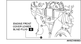
(5) Engine front cover lower blind plug
-
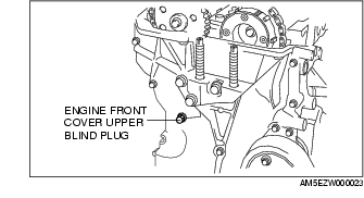
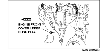
(6) Engine front cover upper blind plug.
-
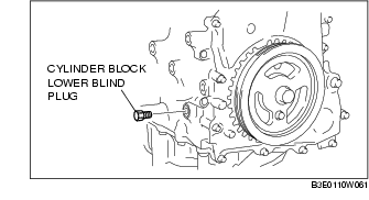
(7) Cylinder block lower blind plug.
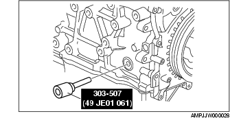
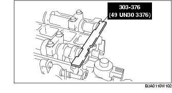
8. Install the SST as shown in the figure.
9. Turn the crankshaft clockwise the crankshaft is in the No.1 cylinder TDC position (until the balance weight is attached to the SST).
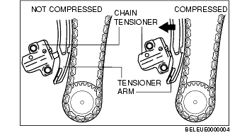
10. Loosen the timing chain using the following procedure:
-
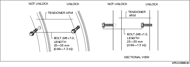
(1) Insert a suitable bolt (M6 X 1.0, length 25-35 mm {0.99-1.3 in}) into the engine front cover upper blind plug and tighten it until it contacts the chain tensioner arm, and then rotate it back one turn. (Set the bolt slightly away from the chain tensioner arm so that it does not contact it.)
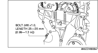
-
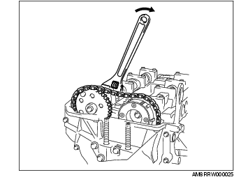
(2) Using the cast hexagon on the exhaust camshaft, apply force counterclockwise to facilitate unlocking the chain tensioner ratchet.

-
(3) Using a Hex bit socket (2.5 mm {0.098 in}) or T15 Torx bit socket, unlock the chain tensioner ratchet so that it can be lifted up.

-
(4) Using the cast hexagon on the exhaust camshaft, apply force in the direction of the engine rotation to increase tension on the chain.
-
Note
-
• The chain tensioner rack is compressed using the chain tension generated by applying force to the exhaust camshaft in the direction of the engine rotation.
-
Note
-
• The ratchet has not been unlocked if the bolt cannot be pressed in approx. 5 mm {0.2 in}.
-
(5) Screw in the bolt set in Step 1 approx. 5 mm {0.2 in}. and secure the tensioner arm with the rack compressed.
-
• If the tensioner arm cannot be secured, return the bolt to its original position and repeat the procedure from Step 3.
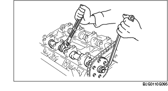
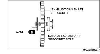
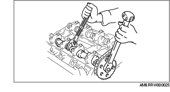
11. Hold the exhaust camshaft using a suitable wrench on the cast hexagon as shown in the figure.
-
Caution
-
• Perform the work carefully so that the washer does not drop out.
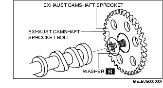
12. Remove the exhaust camshaft sprocket bolt, exhaust camshaft sprocket, and washer as a single unit.
13. Remove the OCV. (L3) (SeeOIL CONTROL VALVE (OCV) REMOVAL/INSTALLATION [L3].)
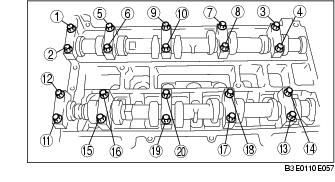
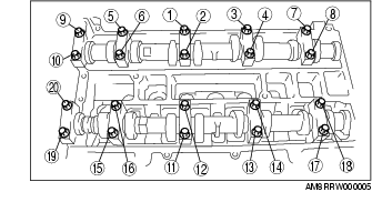
14. Loosen the camshaft cap bolts in 2-3 passes in the order shown in the figure.
-
Note
-
• The cylinder head and the camshaft caps are numbered to be reassembled in their original position correctly. When removed, keep the caps with the cylinder head they were removed from. Do not mix the caps.
15. Remove the camshaft.
16. Remove the tappet.
17. Select proper adjustment shim.
New adjustment shim
-
= Removed shim thickness + Measured valve clearance - Standard valve clearance (IN: 0.25 mm {0.0098 in}, EX: 0.30 mm {0.0118 in})
Standard [Engine cold]
-
IN: 0.22-0.28 mm {0.0087-0.0110 in}
-
EX: 0.27-0.33 mm {0.0107-0.0129 in}
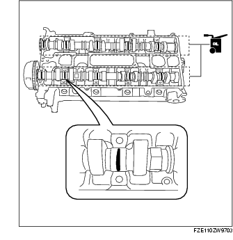
18. Apply the gear oil (SAE No. 90 or equivalent) to each journal of the cylinder head as shown in the figure.
19. Install the camshaft with No.1 cylinder aligned with the TDC position.
20. Apply the gera oil (SAE No. 90 or equivalent) to each journal of the camshaft as shown in the figure.
21. Tighten the camshaft cap bolt with the following 2 steps.
Tightening torque
-
(1) 5.0-8.0 N·m
-
{51.0-81.5 kgf·cm, 44.3-70.8 in·lbf}
-
(2) 14-17 N·m
-
{1.43-1.73 kgf·m, 10.4-12.5 ft·lbf}
22. Install the OCV. (L3) (See OIL CONTROL VALVE (OCV) REMOVAL/INSTALLATION [L3].)
-
Caution
-
• Install a washer to the fourth or fifth thread of the exhaust camshaft sprocket bolt being careful not to drop the washer.
-
• Do not tighten the camshaft sprocket bolt at this stage. Verify the valve timing before performing the bolt tightening.
23. Install the exhaust camshaft sprocket bolt, exhaust camshaft sprocket, and a new washer as a single unit.
24. Install the SST to the camshaft as shown in the figure.
25. Remove the (M6 X 1.0 length 25mm-35mm {0.99-1.37in}) bolt from the engine front cover to apply tension to the timing chain.
26. Turn the crankshaft clockwise until the crankshaft is in the No.1 cylinder TDC position (until the balance weight is attached to the SST).
27. Hold the exhaust camshaft using a suitable wrench on the cast hexagon as shown in the figure.
28. Tighten the exhaust camshaft sprocket bolt.
-
Tightening torque
-
69-75 N·m
-
{7.1-7.6 kgf·m, 50.9-55.3 ft·lbf}
29. Remove the SST from the camshaft.
30. Remove the SST from the block lower blind plug.
31. Rotate the crankshaft clockwise two turns until the TDC position.
-
• If not aligned, loosen the camshaft sprocket bolt and repeat the procedure from Step 24.
32. Apply silicone sealant to the engine front cover upper blind plug.
33. Install the following parts.
-
(1) Engine front cover upper blind plug.
-
Tightening torque
-
8.0-11.5 N·m
-
{81.6-117.2 kgf·cm, 70.9-101.7 in·lbf}
-
(2) Cylinder block lower blind plug.
-
Tightening torque
-
18-22 N·m
-
{1.9-2.2 kgf·m, 13.3-16.2 ft·lbf}
-
(3) New engine front cover lower blind plug.

-
Tightening torque
-
10-14 N·m
-
{1.1-1.4 kgf·m, 7.4-10.3 ft·lbf}
-
(4) Cylinder head cover. (See Cylinder Head Cover Installation Note.)
-
(5) Ignition coils. (See IGNITION COIL REMOVAL/INSTALLATION [LF, L3].)
-
(6) Under cover and splash shield (RH).
-
(7) Front wheel and tire (RH). (See GENERAL PROCEDURES (SUSPENSION).)
34. Connect the ventilation hose.
35. Connect the OCV connector. (L3)
36. Connect the wiring harness.
37. Connect the negative battery cable.
38. Install the battery cover. (See BATTERY REMOVAL/INSTALLATION [LF, L3].)
39. Install the plug hole plate and bracket. (See PLUG HOLE PLATE REMOVAL/INSTALLATION [LF, L3].)