COMBINATION SWITCH REMOVAL/INSTALLATION
id091800469200
1. Disconnect the negative battery cable.
2. Remove the following parts:
-
(1) Driver-side air bag module (See DRIVER-SIDE AIR BAG MODULE REMOVAL/INSTALLATION.)
-
(2) Steering wheel (See STEERING WHEEL AND COLUMN REMOVAL/INSTALLATION.)
-
(3) Front scuff plate (Driver's side) (See FRONT SCUFF PLATE REMOVAL/INSTALLATION.)
-
(4) Front side trim (Driver's side) (See FRONT SIDE TRIM REMOVAL/INSTALLATION.)
-
(5) Bonnet release lever (SeeBONNET LATCH AND RELEASE LEVER REMOVAL/INSTALLATION.)
-
(6) Lower panel (See LOWER PANEL REMOVAL/INSTALLATION.)
-
(7) Column cover (See COLUMN COVER REMOVAL/INSTALLATION.)
-
(8) Clock spring (See CLOCK SPRING REMOVAL/INSTALLATION.)
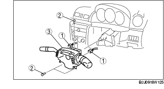
3. Remove in the order indicated in the table.
|
1
|
Connector
|
|
2
|
Screw
|
|
3
|
Combination switch
|
4. Disconnect the steering angle sensor connector. (Vehicles with steering angle sensor)
5. Install in the reverse order of removal.
Combination Switch Removal Note
1. Pull the combination switch locks in the direction indicated in the figure and disengage the tab.
2. Pull the combination switch outward, then remove it.