 |
am6zzw00004350
CYLINDER HEAD GASKET REPLACEMENT [MZR-CD 2.2]
id0110f2800700
1. Complete the “BEFORE SERVICE PRECAUTION”. (See BEFORE SERVICE PRECAUTION [MZR-CD 2.2].)
2. Drain the engine coolant. (See ENGINE COOLANT REPLACEMENT [MZR-CD 2.2].)
3. Drain the engine oil. (See ENGINE OIL REPLACEMENT [MZR-CD 2.2].)
4. Remove the battery and battery tray. (See BATTERY REMOVAL/INSTALLATION [MZR-CD 2.2].)
5. Remove the engine cover. (See ENGINE COVER REMOVAL/INSTALLATION [MZR-CD 2.2].)
6. Remove the air cleaner component and air inlet hose. (See INTAKE-AIR SYSTEM REMOVAL/INSTALLATION [MZR-CD 2.2].)
7. Remove the air inlet pipe and turbocharger air outlet pipe. (See INTAKE-AIR SYSTEM REMOVAL/INSTALLATION [MZR-CD 2.2].)
8. Remove the supply pump. (See SUPPLY PUMP REMOVAL/INSTALLATION [MZR-CD 2.2].)
9. Remove the EGR cooler and EGR cooler bypass valve component. (See EGR COOLER REMOVAL/INSTALLATION [MZR-CD 2.2].)
10. Remove the EGR pipe. (See EGR VALVE REMOVAL/INSTALLATION [MZR-CD 2.2].)
11. Remove the intake shutter valve and EGR cooler bypass valve control solenoid valve bracket No.1. (See INTAKE-AIR SYSTEM REMOVAL/INSTALLATION [MZR-CD 2.2].)
12. Disconnect the upper radiator hose.
13. Remove the boost sensor. (See COMMON RAIL REMOVAL/INSTALLATION [MZR-CD 2.2].)
14. Set the dipstick pipe out of the way.
am6zzw00004350
|
15. Remove the glow plugs. (See GLOW PLUG REMOVAL/INSTALLATION [MZR-CD 2.2].)
16. Remove the bypass pipe.
am6zzw00004351
|
17. Remove the engine coolant temperature sensor. (See ENGINE COOLANT TEMPERATURE (ECT) SENSOR REMOVAL/INSTALLATION [MZR-CD 2.2].)
18. Disconnect the heater hose.
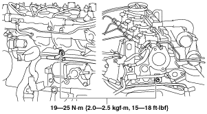
19. Remove the turbocharger. (See EXHAUST SYSTEM REMOVAL/INSTALLATION [MZR-CD 2.2].)
20. Remove the timing chain. (See TIMING CHAIN REMOVAL/INSTALLATION [MZR-CD 2.2].)
21. Remove the seal plate. (See OIL PAN REMOVAL/INSTALLATION [MZR-CD 2.2].)
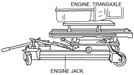
22. To firmly support the engine, first set the engine jack to the oil pan.
am5ezw00000575
|
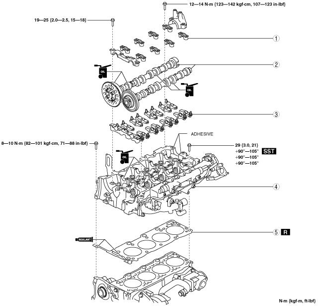
23. Remove in the order shown in the table.
24. Install in the reverse order of removal.
25. Complete the “AFTER SERVICE PRECAUTION”. (See AFTER SERVICE PRECAUTION [MZR-CD 2.2].)
26. Refill the engine oil. (See ENGINE OIL REPLACEMENT [MZR-CD 2.2].)
27. Refill the engine coolant. (See ENGINE COOLANT REPLACEMENT [MZR-CD 2.2].)
28. Inspect the valve clearance. (See VALVE CLEARANCE INSPECTION [MZR-CD 2.2].)
29. Inspect the compression. (See COMPRESSION INSPECTION [MZR-CD 2.2].)
30. Start the engine. And inspect and adjust the following:
am6zzw00007290
|
|
1
|
Camshaft cap
(See Camshaft Cap Removal Note.)
|
|
2
|
Camshaft
(See Camshaft Installation Note.)
|
|
3
|
Rocker arm
(See Rocker Arm Installation Note.)
|
|
4
|
Cylinder head
(See Cylinder Head Removal Note.)
|
|
5
|
Cylinder head gasket
|
Camshaft Cap Removal Note
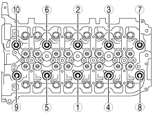
1. Loosen the bolts in three or more steps in the order shown in the figure.
am6zzw00004255
|
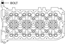
Cylinder Head Removal Note
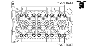
1. Remove the bolt shown in the figure.
am6zzw00004298
|
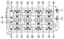
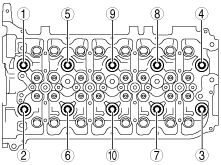
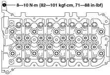
2. Loosen the bolts in two or three steps in the order shown in the figure.
am6zzw00004258
|
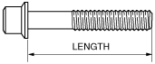
Cylinder Head Installation Note
1. Measure the length of each cylinder head bolt.
am6zzw00004294
|
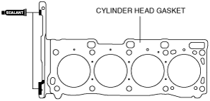
2. Apply sealant as shown in the figure.
am6zzw00004259
|
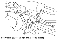
3. Tighten the bolts using the following procedure.
am6zzw00004256
|
am6zzw00004299
|
Rocker Arm Installation Note
1. Apply engine oil to the dented surface of the pivot bolt for the adjust screw.
am6zzw00004295
|
2. Install the rocker arms.
Camshaft Installation Note
1. Apply the gear oil (SAE No.90 or equivalent) to each journal of the cylinder head.
2. Apply engine oil to the sliding surface of the exhaust camshaft drive gear and the intake camshaft driven gear.
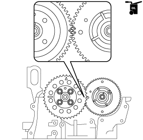
3. Align the gear marks of the exhaust camshaft drive gear and the intake camshaft driven gear and install the parts to the cylinder head.
am6zzw00004296
|
4. Apply the gear oil (SAE No.90 or equivalent) to each journal of the camshaft.
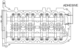
Camshaft Cap Installation Note
1. Apply adhesive as shown in the figure.
am6zzw00007291
|
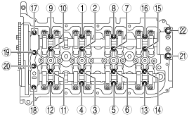
2. Tighten the bolts in three or more steps in the order shown in the figure.
am6zzw00004470
|