 |
am6zzw00006348
JOINT SHAFT REMOVAL/INSTALLATION
id031300800900
1. Remove the aerodynamic under cover No. 2. (See AERODYNAMIC UNDER COVER NO.2 REMOVAL/INSTALLATION.)
2. Set the front mudguard out of the way. (See FRONT MUDGUARD REMOVAL/INSTALLATION.)
3. Remove the splash shield.
4. Drain the transaxle oil or ATF. (See TRANSAXLE OIL REPLACEMENT [G35M-R].) (See TRANSAXLE OIL REPLACEMENT [G66M-R].) (SeeTRANSAXLE OIL REPLACEMENT [A26M-R].) (See AUTOMATIC TRANSAXLE FLUID (ATF) REPLACEMENT [FS5A-EL].)
5. Disconnect the front auto leveling sensor link. (Vehicle with discharge headlight system) (See AUTO LEVELING SENSOR REMOVAL/INSTALLATION.)
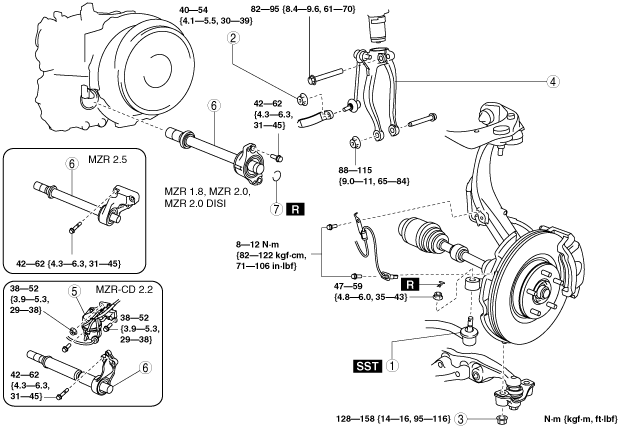
6. Remove in the order indicated in the table.
7. Install in the reverse order of removal.
am6zzw00006348
|
|
1
|
Tie-rod end ball joint
|
|
2
|
Nut (front stabilizer control link lower side)
|
|
3
|
Nut (lower arm)
|
|
4
|
Damper fork
|
|
5
|
Vacuum chamber (MZR-CD 2.2)
(See Vacuum Chamber Removal Note.)
|
|
6
|
Joint shaft
(See Joint Shaft Removal Note.)
|
|
7
|
Clip
(See Clip Installation Note.)
|
Vacuum Chamber Removal Note
1. Remove the vacuum chamber bracket installation nut and bolts and set the vacuum chamber aside so that it is out of the way.
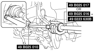
Joint Shaft Removal Note
1. Disconnect the drive shaft (RH) from the joint shaft by using the SSTs.
am6zzw00004451
|
2. Disconnect the clips to set the CKP sensor harness out of the way to prevent interference with the joint shaft. (MZR 2.5)
3. Disconnect the joint shaft bracket from the cylinder block and remove the joint shaft.
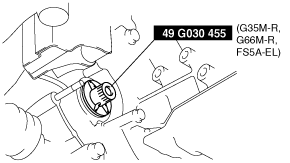
4. Install the SST to the transaxle after the joint shaft is removed.
am6zzw00009567
|
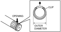
Clip Installation Note
1. Install a new joint shaft clip to the clip groove at the end of the joint shaft with the clip opening facing upward and the clip width within the specification.
2. After installation, measure the outer diameter.
am3zzw00004379
|